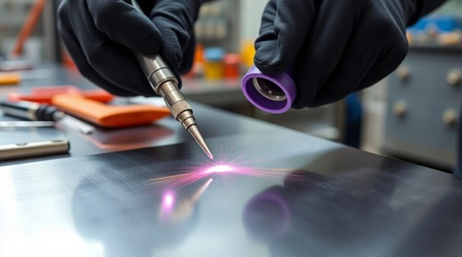
Cleaner TIG beads begin before the arc is struck. A clean surface, correctly prepared tungsten, suitable cup, steady shielding gas, short arc, and controlled heat all affect the finished weld. Once the arc starts, the goal is simple: keep the puddle predictable, feed filler into its leading edge, and avoid introducing contamination while the weld and tungsten are hot.
Quick Answer
For cleaner TIG beads, remove oil, oxide, paint, and mill scale; use clean filler and properly prepared tungsten; keep a short, steady arc; push the torch at a slight angle; maintain effective argon coverage; and adjust amperage and travel speed so the puddle stays controlled instead of growing excessively hot.
Key Takeaways
- Clean both the base metal and filler before welding; contamination is one of the most common causes of porosity, discoloration, and an unstable arc.
- Select tungsten type and diameter for the machine, polarity, material, and amperage instead of using one electrode for every job.
- Keep the TIG arc short and consistent, usually around 1/16 to 1/8 inch for common manual work unless the procedure or equipment calls for something different.
- Push the torch with a modest travel angle and add filler at the leading edge of the puddle without touching the tungsten.
- Use enough shielding gas for complete coverage, but do not assume more flow is better; excessive flow can create turbulence and contamination.
- Control heat with amperage, travel speed, filler timing, and a foot pedal or torch control when available.
At a Glance
| Time Required | About 15–30 minutes for setup and preparation, plus practice time |
| Difficulty | Beginner to intermediate; consistent TIG technique takes repeated practice |
| Tools Needed | TIG welder, torch, correct tungsten and cup, argon and flowmeter, filler rod, dedicated tungsten grinder, cleaning tools, and welding PPE |
| Cost | Variable; mainly shielding gas, tungsten, filler rod, and cleaning supplies when welding equipment is already available |
Warning: TIG welding exposes the operator to intense ultraviolet radiation, heat, hot metal, electric-shock hazards, and welding fumes. Wear suitable eye, face, skin, hand, and foot protection and provide adequate ventilation. Never weld near chlorinated-solvent vapors or use chlorinated degreasers around the welding area; ultraviolet radiation from gas-shielded welding can contribute to formation of highly toxic decomposition products.
Clean Metal Before TIG Welding
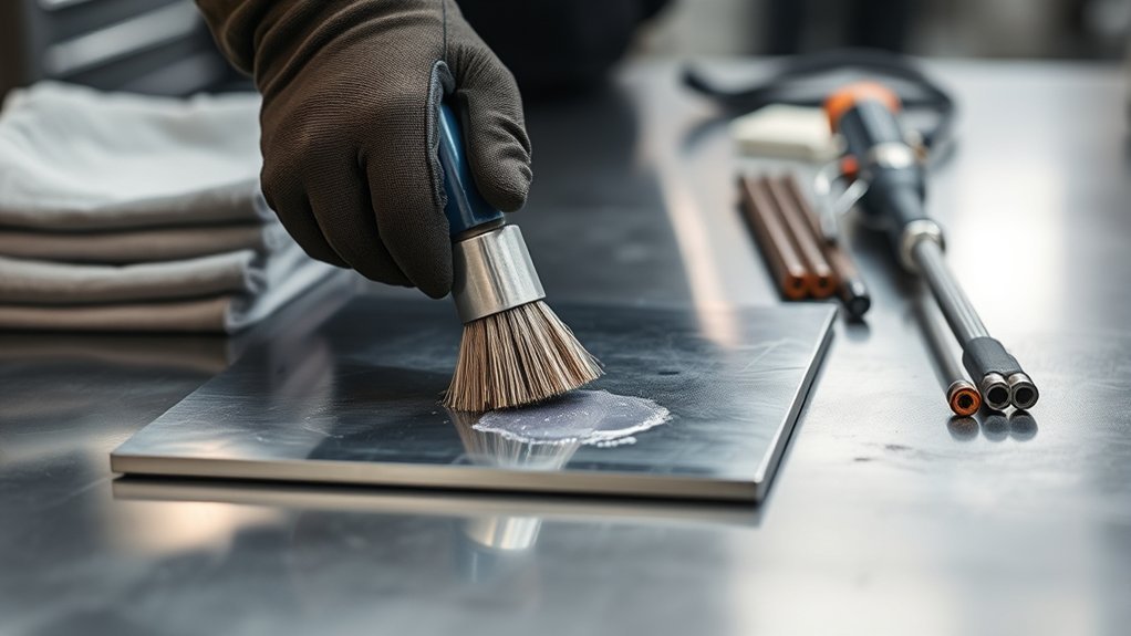
Before TIG welding, the metal should be thoroughly cleaned to remove rust, paint, oil, mill scale, oxide, moisture, and other contaminants that can interfere with the arc or enter the weld pool.
Cleaning method depends on the metal. On mild steel, grinding, sanding, or wire brushing may be needed to expose clean metal. Aluminum needs special care because its oxide layer melts at a much higher temperature than the aluminum underneath. A dedicated stainless-steel wire brush used only for aluminum helps avoid cross-contamination.
For oily material, first use a suitable residue-free, non-chlorinated cleaner according to its safety instructions. After the solvent has fully evaporated, mechanically clean the joint as needed. Miller’s aluminum cleaning guidance specifically recommends keeping aluminum cleaning tools dedicated to that material.
A grinder or wire brush can remove heavy scale and surface debris, but the tool itself must be clean. A contaminated brush or abrasive can move oil, steel particles, or other residue onto the weld area instead of removing it.
Heavy-duty cleaners should not be chosen simply because they are aggressive. Use a cleaner suitable for the base metal and welding environment, follow its safety data, and avoid chlorinated solvents around an active welding arc. OSHA’s welding, cutting, and brazing requirements address ventilation, PPE, and cleaning-compound hazards.
Clean metal supports a steadier arc, reduces tungsten contamination, and improves bead appearance. It also reduces the chance of porosity, inclusions, lack of fusion, and other defects. Equipment condition matters as well; a TIG machine with good build quality and stable output makes precise control easier, but it cannot compensate for dirty material.
Pro Tip: Clean the filler rod as well as the workpiece. Keep cleaned filler in a dry location and avoid handling the portion that will enter the shielding-gas envelope with oily gloves.
Choose the Right Tungsten and Cup Size
Choosing the right tungsten and cup size helps establish a stable arc and dependable shielding-gas coverage. There is no single tungsten type that is best for every TIG machine and material, so check the welder manufacturer’s recommendations before treating a color or alloy as a universal choice.
Lanthanated and ceriated tungsten are common choices on modern TIG equipment. Modern inverter-based AC machines can use alloyed electrodes effectively for aluminum, while zirconiated tungsten remains suitable for some AC applications. Miller’s current AC TIG tungsten guidance explains why modern inverter machines no longer require the traditional pure-tungsten approach.
Tungsten selection should match the machine, polarity, amperage, and material—not just the metal being welded.
For a pointed electrode, grind the tungsten lengthwise so the grinding marks run parallel to the electrode axis. Use a grinder or wheel reserved for tungsten to reduce contamination. A sharp-to-truncated point is common for controlled arcs, while the exact geometry depends on current and application.
Cup size should match access and shielding needs. Larger cups can provide broader coverage, while smaller cups improve access in tight joints. A gas lens straightens gas flow and can permit more tungsten extension than a standard collet-body setup.
For a conventional setup, approximately 1/8 to 1/4 inch of tungsten extension is a useful starting range, but joint geometry and the gas system can change that. Do not treat 3 mm as a fixed limit. The AC/DC functionality of the machine also matters because aluminum and steel typically use different current modes.
Feed Filler Rod Smoothly Into the Pool
With the arc stabilized by the correct tungsten and cup setup, attention shifts to feeding the filler rod smoothly into the weld pool. Hold the rod comfortably enough that the fingers can advance it without jerking the torch hand.
Rather than exposing an exact fixed length such as 10 cm for every job, extend enough rod for comfortable feeding while maintaining control. Long unsupported filler can wobble, while too little extension forces frequent hand repositioning.
Add filler at the leading edge of the puddle. The rod should melt from contact with the molten pool and arc zone rather than being deliberately melted against the tungsten. Touching the tungsten with filler contaminates the electrode and usually requires stopping and regrinding it.
The filler tip should stay inside or very near the shielding envelope between dabs. Pulling a hot filler tip completely into the atmosphere allows oxidation to form; repeatedly feeding that oxidized end back into the puddle can hurt bead cleanliness.
Steady, rhythmic feeding builds coordination and helps produce clean, consistent beads. A capable TIG welder can provide stable output, but consistent hand movement is still essential.
Hold the Right Torch Angle and Arc Length
Control of torch angle and arc length directly affects TIG bead shape and puddle control. For many flat-position welds, a modest push angle of about 10–20 degrees from vertical provides visibility while keeping the gas shield centered over the puddle.
Keep the tungsten close without touching the work. Miller’s current TIG welding basics guide uses approximately 1/16 to 1/8 inch as a common electrode-to-work range. The exact distance still depends on the joint, current, tungsten, and procedure.
A long arc increases arc voltage and spreads the heat over a wider area. It can make the puddle harder to control and leave the shielding gas more vulnerable to surrounding air. An arc that is too short increases the chance of dipping the tungsten.
- Use a slight push angle rather than leaning the torch sharply.
- Keep the arc short and consistent.
- Adjust your hand position as the joint geometry changes.
- Brace your torch hand when practical to reduce unwanted movement.
- Keep the filler ahead of the torch and add it at the puddle’s leading edge.
This controlled approach supports a uniform bead and is especially helpful for a beginning operator using a beginner-friendly welder.
Keep Shielding Gas on the Weld
Shielding gas must protect the tungsten, arc, molten puddle, and hot weld as they cool. For general TIG work, 100% argon is the most common shielding gas. Argon/helium mixtures are also used for applications that need additional heat input.
Gas flow is not a “more is better” setting. Miller’s current TIG shielding-gas guidance gives a broad typical range of 10–35 cubic feet per hour depending on consumables and conditions. Around 15–20 cfh, roughly 7–9.5 L/min, is a common starting point for many ordinary setups.
Too little flow can leave the puddle exposed to air, but excessive flow can create turbulence and pull atmospheric gases into the shielding stream. Cup size, gas-lens design, drafts, tungsten extension, joint shape, and torch position all affect the amount of flow required.
A gas lens helps produce more uniform gas coverage. It is especially useful when additional tungsten extension is necessary for access. Keep the hot filler rod tip within the gas envelope whenever practical.
During long runs or awkward joints, watch for signs of shielding trouble: gray or black deposits, tungsten discoloration, porosity, unstable arc behavior, or unusual bead color. Check gas flow, fittings, torch assembly, hoses, cup condition, and drafts before simply turning the flow higher.
For shops that also use a multi-process welder, confirm that the gas and machine configuration have actually been changed for TIG rather than assuming the previous MIG setup is suitable.
Control Heat for Cleaner TIG Beads
Heat input must be matched to the material, joint design, thickness, travel speed, and welding position. A maximum-amperage setting is only part of the equation. With a foot pedal or torch-mounted amperage control, the welder can establish the puddle quickly and reduce current as heat builds in the workpiece.
Watch the puddle rather than staring only at the machine display. A controlled puddle should remain predictable in width and shape. If it becomes progressively wider, brighter, or harder to contain, heat is accumulating faster than the weld is moving.
- Reduce amperage when thin material begins to sag or the puddle grows too quickly.
- Increase travel speed if the joint is overheating despite adequate fusion.
- Use enough initial current to establish the puddle instead of dwelling too long at low current.
- Add filler consistently; filler absorbs heat and changes puddle behavior.
- Ease off current near the end of the weld to help fill the crater instead of stopping abruptly.
- Keep the torch over the weld during post-flow so the cooling tungsten and weld remain shielded.
Heat control also depends on comfort and dexterity. Gloves designed for fingertip sensitivity can make filler feeding easier while still providing appropriate welding protection.
Note: Settings found online are starting points, not qualified welding procedures. For code work or safety-critical parts, follow the applicable welding procedure specification, material requirements, machine manual, and inspection criteria.
Read the Puddle and Adjust Travel Speed
Cleaner TIG beads come from reacting to the puddle while welding. The puddle tells you whether heat, arc length, filler timing, and travel speed are working together.
| What You See | Likely Cause | What to Check |
|---|---|---|
| Puddle keeps getting wider | Heat buildup or slow travel | Reduce current gradually or increase travel speed |
| Narrow bead with poor fusion | Insufficient heat, excessive travel speed, or poor fit-up | Check amperage, joint preparation, arc placement, and speed |
| Arc wanders | Long arc, contaminated or poorly ground tungsten, or setup issue | Shorten arc, inspect tungsten, verify polarity and connections |
| Gray, black, or porous weld | Contamination or inadequate shielding | Clean material, check gas, leaks, drafts, cup, filler, and post-flow |
| Tungsten repeatedly dips | Arc is too short or torch/filler hands are moving together | Brace the torch hand and practice filler movement separately |
Practice TIG Bead Pads for Consistency
Practice TIG bead pads on clean mild-steel plate to build control over torch angle, arc length, puddle size, travel speed, and filler timing. Plate around 1/8 to 1/4 inch thick gives beginners enough thermal mass for useful practice without making heat control impossible.
Each bead can overlap the previous bead by roughly 50 percent when the goal is to build a uniform practice pad. The objective is not simply to cover the plate; it is to make repeated beads with similar width, reinforcement, and spacing.
Monitor heat input as the plate becomes progressively hotter. If the puddle grows faster during later beads, either reduce current, increase travel speed, move to a cooler area, or pause and allow the plate to cool naturally before continuing. A suitable welder for home use can handle practice work, but machine output should always be matched to the plate and duty cycle.
Bead Pad Basics
A bead pad on clean mild steel gives the welder a controlled way to develop TIG consistency. ER70S-2 or another filler appropriate for the steel and procedure may be used, but filler selection should match the actual base metal rather than being chosen only because it is convenient.
The original 110–140 amp recommendation can be a usable maximum-current starting area for some 1/8-inch mild-steel practice, but it is not a universal setting. Joint configuration, tungsten size, torch, machine, actual plate thickness, travel speed, and pedal control all affect the required current.
- Start with a clean plate and clean filler.
- Set the machine for the correct polarity and tungsten.
- Establish a small, repeatable puddle before adding filler.
- Hold a short, consistent arc.
- Keep travel speed even.
- Watch heat buildup from one bead to the next.
Practice first without filler if hand coordination is difficult. Once puddle movement is consistent, introduce filler and focus on adding similar amounts at regular intervals.
Overlap For Consistency
Consistent bead pads often use roughly 50% overlap from one bead to the next. This makes differences in bead width, travel speed, and filler timing easier to see.
With overlapping TIG beads, steady travel speed and controlled arc length keep the puddle predictable. If the puddle begins to spread or sag, reduce heat or increase pace rather than continuing with the same settings.
After several beads, allow the plate to cool when accumulated heat starts changing the exercise. Avoid using an uncontrolled quench merely to keep practicing unless the material and procedure specifically permit it.
Repeated bead-pad practice builds filler timing, torch stability, heat management, and puddle awareness. Photographing or comparing each group of beads can also help identify whether consistency is improving.
Fix TIG Weld Contamination Issues
When TIG welds suddenly become dirty, do not immediately blame amperage. Work through the contamination path in order: base metal, filler, tungsten, gas supply, torch assembly, airflow, polarity, and technique.
Proper tungsten preparation matters, but a freshly ground tungsten will become contaminated again if the underlying cause remains. A correct electrode type and diameter, clean grind, short arc, and adequate shielding all work together.
The filler rod should remain within the shielding-gas envelope as much as practical, especially while its tip is hot. When switching between materials, keep brushes, abrasives, and other preparation tools separated where cross-contamination matters.
Machine process capability also matters. A Hobart Handler 140 vs Lincoln 140 Easy MIG comparison concerns MIG machines, for example, and its settings should not be transferred to TIG merely because the base metal thickness is similar.
Clean Base Metal Thoroughly
Thorough preparation is essential for preventing TIG weld contamination. Strip the weld zone of rust, paint, oil, scale, oxide, moisture, and other contaminants before striking the arc.
Mechanical cleaning removes heavy debris, while an appropriate residue-free cleaner can remove grease and oils. For aluminum, solvent cleaning should normally happen before final stainless-wire brushing so hydrocarbons are not driven into the surface.
- Remove visible coatings, scale, dirt, and oxidation.
- Degrease with a suitable non-chlorinated cleaner when needed.
- Use clean, material-appropriate brushes and abrasives.
- Clean the filler rod if it has been exposed to dirt or oil.
- Inspect the joint again immediately before welding.
If contamination persists after cleaning the visible surface, inspect the back side of the joint and any cracks, pores, seams, or old repairs where oil or coatings may remain.
Prevent Tungsten And Filler Contamination
Keeping the tungsten and filler metal clean is critical for stable TIG performance. If the tungsten touches the weld pool or filler, stop and correct it rather than trying to continue through obvious contamination.
A grinder reserved for tungsten helps prevent foreign particles from entering the electrode. Grinding scratches should run lengthwise. After grinding, keep the electrode clean during installation.
| Action | Result |
|---|---|
| Avoid tungsten dips | More stable arc and less contamination |
| Use a dedicated tungsten grinder | Cleaner electrode preparation |
| Keep hot filler within the gas shield | Less oxidation on the filler tip |
| Use dedicated cleaning tools where needed | Lower cross-contamination risk |
| Regrind contaminated tungsten | Restored arc focus |
If contamination appears, regrind or replace the tungsten as appropriate instead of attempting to burn contamination away while welding.
Troubleshoot Dirty or Porous TIG Welds
| Problem | Likely Checks |
|---|---|
| Porosity | Dirty base metal or filler, moisture, gas leak, inadequate shielding, excessive gas turbulence |
| Black or gray deposit | Poor gas coverage, dirty material, wrong polarity, contaminated tungsten, excessive stick-out |
| Tungsten turns dull or oxidized | Insufficient post-flow, gas interruption, leak, contaminated gas path |
| Unstable or wandering arc | Long arc, poor tungsten preparation, contamination, wrong electrode size, loose connection |
| Repeated tungsten melting | Incorrect polarity, too much current for tungsten size, inadequate shielding, unsuitable electrode setup |
Miller’s common TIG welding problems guide identifies gas coverage, polarity, contamination, long arc length, and incorrect tungsten setup among the common causes of poor TIG results.
Finish TIG Welds Cleanly
A clean TIG weld depends on prepared material, stable shielding, appropriate heat, and a controlled finish. TIG normally produces no slag, so heavy post-weld cleanup should not be needed merely to make a sound bead look acceptable.
As the weld approaches its end, reduce current smoothly when the equipment and procedure allow it and add enough filler to avoid leaving a deep crater. Abruptly stopping on a hot, underfilled crater can leave a weak termination point.
After the arc stops, keep the torch over the end of the weld while post-flow gas continues. Post-flow protects both the cooling weld and hot tungsten. Miller’s shielding-gas guidance recommends sufficient post-flow for the welding current and emphasizes holding the torch in place until the post-flow ends.
For typical TIG work, use argon or another gas approved for the procedure. A MIG shielding gas guide covers a different process; MIG argon/CO2 mixtures should not be treated as interchangeable with TIG shielding gas.
A clean TIG bead is usually the result of several small controls working together: clean metal, clean tungsten, short arc length, correct shielding, steady movement, and controlled heat.
- Clean the work and filler before welding.
- Use the correct polarity, tungsten, and consumables.
- Keep shielding gas steady and free from leaks or drafts.
- Push the TIG torch with a modest angle.
- Match current and travel speed to the changing puddle.
- Protect the hot weld and tungsten with adequate post-flow.
Frequently Asked Questions
What Is the Rule of 33 in TIG Welding?
The TIG “Rule of 33” is an informal starting point for high-speed pulsed TIG welding: roughly 33 pulses per second, 33% pulse or peak-on time, and 33% background current. It is not a rule requiring 3 inches per minute of travel for every 1/8 inch of material, and it is not a universal AWS welding standard. Treat it as a pulse-setting experiment that may need significant adjustment for the joint and material.
How Do You Weld a Cleaner, More Consistent TIG Bead?
Start with clean base metal, filler, and tungsten. Keep the arc short, use a slight push angle, establish a stable puddle, and feed similar amounts of filler into its leading edge. Adjust amperage or travel speed as the work heats up, then taper the finish and keep the torch in place during post-flow.
Do You Push or Drag When TIG Welding?
TIG is normally performed with a push, or forehand, technique. Point the tungsten slightly in the direction of travel and add filler at the leading edge of the puddle. A modest travel angle, commonly around 10–20 degrees from vertical, provides visibility without directing the gas shield away from the weld.
What Are Some Useful TIG Welding Tips?
Clean the work and filler, grind tungsten lengthwise on a dedicated wheel, keep the arc short, brace the torch hand when possible, keep the filler tip shielded, use the lowest gas flow that provides complete coverage, and practice puddle movement before trying to coordinate filler. Regrind tungsten immediately after a dip.
How Much Argon Flow Should You Use for TIG Welding?
There is no single flow setting for every TIG job. Around 15–20 cfh is a common starting range for many ordinary setups, while the correct value depends on cup size, gas lens, tungsten extension, joint geometry, drafts, and the welding procedure. Too much flow can create turbulence, so increasing the flow is not always the solution to contamination.
Why Does a TIG Weld Turn Gray, Black, or Porous?
Common causes include dirty base metal or filler, inadequate shielding gas, excessive gas turbulence, leaks, drafts, contaminated tungsten, excessive arc length, incorrect polarity, or insufficient post-flow. Check the entire gas and cleanliness path before changing amperage at random.
Conclusion
Cleaner TIG beads come from repeatable preparation and control rather than one special machine setting. Start with clean metal and filler, prepare the tungsten correctly, maintain reliable shielding, keep the arc short, push the torch steadily, and adjust heat as the puddle changes.
When a bead becomes dirty or inconsistent, stop and diagnose the cause instead of welding through it. Check the tungsten, material, filler, gas coverage, polarity, connections, and technique in a logical order. Regular bead-pad practice makes those corrections easier to recognize and turns clean TIG welding into a repeatable process rather than guesswork.
Sources
- Miller — Guide to TIG Welding Basics — TIG setup, arc length, tungsten preparation, filler technique, gas flow, and troubleshooting.
- Miller — Best Practices for Proper Shielding Gas in TIG Welding — shielding-gas selection, flow, gas lenses, turbulence, pre-flow, and post-flow.
- Miller — Common TIG Welding Problems — contamination, polarity, gas coverage, fusion, tungsten, and arc troubleshooting.
- Miller — Cleaning and Preparing Aluminum Before Welding — oxide removal, dedicated brushes, solvent cleaning, and contamination prevention.
- OSHA — 29 CFR 1910.252 Welding, Cutting, and Brazing — PPE, ventilation, cleaning compounds, and welding safety requirements.