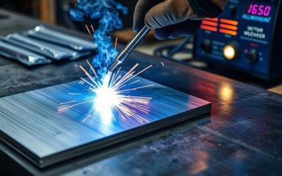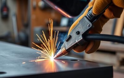
Welding bead patterns show how the arc, electrode, or torch moved along a joint, but appearance alone does not determine weld strength. A straight stringer bead keeps side-to-side movement to a minimum, while a weave bead deliberately moves across the joint to cover more width. The right technique depends on the welding process, joint design, position, material, consumable, settings, and any welding procedure specification (WPS) that applies.
Quick Answer
A stringer bead travels mostly straight along the joint and produces a relatively narrow pass. A weave bead moves side to side to cover a wider area. Neither pattern automatically guarantees penetration or strength. Choose the motion according to the process, joint width, welding position, consumable instructions, machine settings, and the WPS when one applies.
Key Takeaways
- A weld bead is the weld metal produced by a weld pass; it is not necessarily just deposited filler metal.
- Stringer beads use little lateral movement and are useful for narrow passes, roots, many multi-pass welds, and positions where a small puddle is easier to control.
- Weave beads move side to side and can help cover wider joints or improve sidewall tie-in when the process and procedure permit weaving.
- Penetration depends on more than the motion pattern. Current, voltage, travel speed, polarity, joint preparation, electrode or wire, arc length, and process all matter.
- Vertical-up welding may use controlled side-to-side or triangular techniques, while overhead welding commonly favors small stringer passes.
- A smooth-looking bead does not prove complete fusion or internal weld quality.
Warning: Arc welding can expose you to ultraviolet and infrared radiation, hot metal, fumes and gases, electrical shock, sparks, and fire hazards. Wear suitable eye, face, hand, body, and foot protection; provide appropriate ventilation; remove or protect combustible materials; and follow your equipment instructions and workplace hot-work procedures. OSHA provides current guidance for welding, cutting, and brazing hazards.
What Is a Welding Bead?
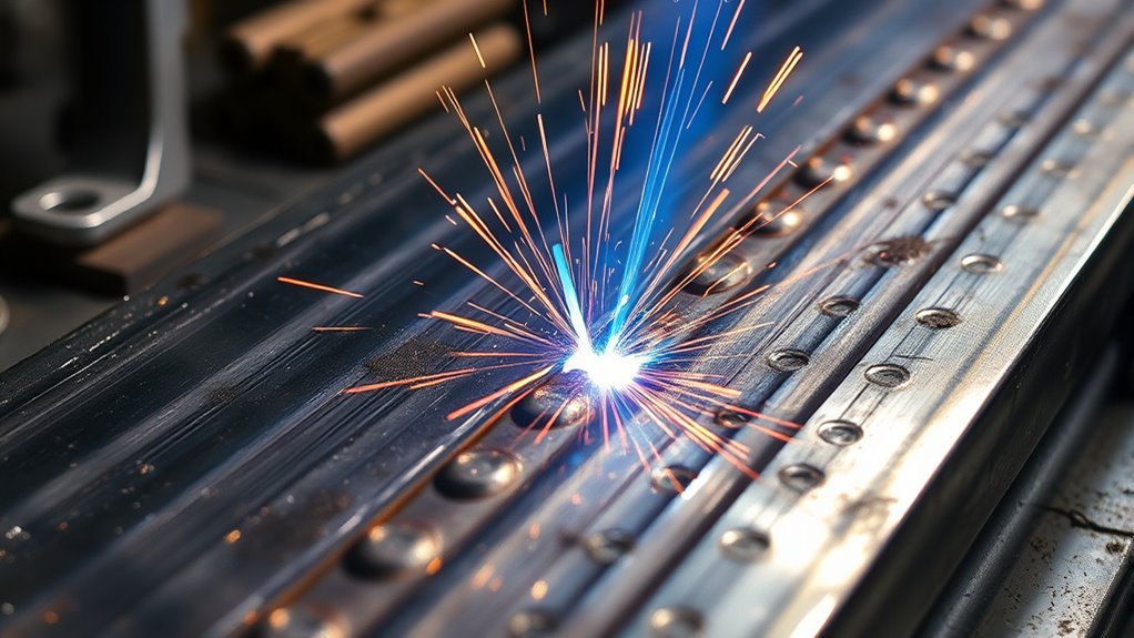
A welding bead is the weld metal produced as the arc, flame, or other welding heat source progresses along a joint. In a fusion weld, the bead can contain melted base metal plus added filler metal. Some welding techniques can also be performed without added filler, so a weld bead should not be defined simply as a line of filler material.
The bead records what happened during the weld. Its width, crown or reinforcement, toe shape, ripple consistency, and surface condition can reveal useful clues about travel speed, arc length, heat input, torch or electrode angle, filler delivery, and puddle control.
Visual appearance is useful, but it has limits. A bead can look smooth and still contain lack of fusion, incomplete penetration, porosity, slag inclusions, or other discontinuities that cannot be confirmed from the surface alone.
The American Welding Society maintains standardized welding terminology through its current AWS A3.0M/A3.0:2025 welding terminology standard, which helps keep terms such as weld pass, weld metal, and related inspection language consistent across the industry.
Basic Weld Bead Anatomy
Understanding a few bead features makes it easier to diagnose technique problems:
- Face: The exposed surface of the completed weld.
- Toes: The edges where the weld face meets the base metal.
- Width: The distance between the weld toes.
- Reinforcement or crown: Weld metal extending above the surrounding surface on applicable groove welds.
- Root: The portion of the joint farthest from the weld face; root fusion and penetration cannot always be judged from the visible face.
Note: A uniform “stacked” appearance can indicate consistent hand movement, but cosmetic ripples are not a substitute for correct weld size, fusion, penetration where required, or compliance with the applicable WPS and acceptance criteria.
Torch Movements That Shape Weld Beads
Torch or electrode movement influences weld bead width, puddle shape, heat distribution, and toe tie-in. The two broad categories are stringer beads and weave beads, but the final result also depends on process settings and joint geometry.
Travel speed is particularly important. Moving too slowly can create an excessively wide or convex bead and may direct too much arc energy into the molten puddle instead of the unfused base metal. Moving too fast can create a narrow, undersized bead, reduce penetration, and contribute to undercut. Miller discusses these relationships in its stick-welding technique guidance.
Stringer Bead Control
A stringer bead is made by progressing along the joint with little or no deliberate side-to-side oscillation. The goal is a controlled, relatively narrow pass rather than a wide deposit.
- Keep a consistent travel speed so the puddle size remains predictable.
- Maintain the arc length or contact-tip-to-work distance recommended for the process.
- Use the travel and work angles appropriate for the joint and welding process.
- Watch both weld toes so the bead ties into the base metal instead of merely sitting on top.
- For a wide groove, multiple overlapping stringers may be preferable to one large weave.
Stringers are common for root passes, multi-pass work, thin materials, and out-of-position welding where keeping the molten pool small improves control. However, a straight pass does not automatically produce deep penetration. Penetration still depends on current, voltage, polarity, consumable, joint preparation, electrode or wire placement, and travel speed.
Weave Motion Patterns
A weave bead uses controlled lateral movement while the weld progresses forward. The motion increases bead width and can help the arc reach both sidewalls of a wider groove or fillet.
Common shop descriptions include zig-zag, crescent, triangular, circular, box, and ladder-style motions. These names are useful for describing hand movement, but they should not be treated as universal prescriptions. The suitable movement depends on the process, electrode or wire, transfer mode, joint, welding position, and procedure.
When a weave is appropriate, brief controlled pauses near the sides can help achieve tie-in at the toes. Spending too long at an edge or making the weave excessively wide can increase heat input, enlarge the puddle, worsen distortion, or create fusion and slag-control problems.
Pro Tip: If a joint is too wide for one comfortable bead, do not assume you need a larger weave. Multiple smaller stringer passes often provide easier puddle control, especially overhead or when the welding procedure limits weave width.
Stringer Beads for Controlled, Narrow Passes
Stringer beads keep the arc focused along a relatively narrow path by minimizing side-to-side movement. This can make heat placement and puddle control easier, especially during root passes, multi-pass welds, and difficult welding positions.
- Advance at a steady pace rather than racing ahead of the puddle.
- Keep the arc directed where fusion is needed.
- Maintain a stable travel angle and arc length.
- Use overlapping passes when a wider joint must be filled.
- Clean between passes when the process produces slag.
A stringer can provide good penetration when the joint, consumable, settings, and travel speed are correct, but the movement pattern itself is only one variable. Excessively fast travel can reduce penetration, while excessively slow travel can create a large puddle that contributes to poor fusion or excessive buildup.
Stringers can also reduce the amount of metal deposited per pass compared with a wide weave. That can mean more passes, but smaller individual puddles are often easier to inspect and control.
Weave Patterns for Wider Joints
Weave patterns can cover a wider joint in one pass by moving the arc from side to side. They are useful in some groove and fillet welds, particularly when sidewall tie-in is important and the procedure allows the additional oscillation.
Weaving is not automatically better than multiple stringers. A wide weave generally keeps the arc in one area longer and creates a larger molten pool, so heat input, distortion, slag behavior, and position become important considerations.
Triangle Weaves for Vertical-Up Welding
A triangular weave is one technique used in some vertical-up welds. Lincoln Electric guidance for applicable electrodes describes triangular movement on larger vertical-up fillets, with controlled hesitation near the outer edges and attention to directing the arc into the joint rather than simply riding on the puddle.
The purpose is not to make a decorative triangle. The welder is trying to manage the molten pool against gravity while achieving sidewall tie-in and progressing upward at a controlled rate.
- Keep the arc and puddle small enough to control.
- Pause only as long as needed for sidewall tie-in.
- Move across the center without allowing excessive buildup.
- Follow the electrode manufacturer’s instructions and WPS limits.
Curlicue Patterns for Fill
A curlicue or circular-style pattern uses repeated oval or circular movements while progressing along the joint. It can create a wider deposit and may be useful for fill work when the process, position, and procedure permit that motion.
The key is consistency rather than the artistic shape of the pattern. The arc still needs to reach the areas requiring fusion, and the puddle must remain controllable. Excessive circular movement can unnecessarily enlarge the bead, increase heat input, and make it harder to maintain equal tie-in at both toes.
For vertical or overhead work, keep the molten pool particularly small. In many overhead applications, multiple stringer beads provide better control than a wide circular weave.
Ladder Motion for Evenness
A ladder-style movement is another shop term for a stepped side-to-side progression. Its purpose is to spread deposition across a wider area while giving the welder clear reference points at the two sides of the joint.
- Keep each lateral movement consistent.
- Avoid long pauses that create excessive buildup at the toes.
- Watch the leading edge of the puddle instead of following the finished ripple pattern.
- Do not exceed weave restrictions in the applicable procedure or consumable instructions.
Pattern names such as ladder, curlicue, crescent, and zig-zag describe hand motion, not guaranteed mechanical properties. Weld strength depends on the completed joint, fusion, weld size, material, procedure, and absence of unacceptable discontinuities.
What Controls Weld Penetration and Bead Shape?
Bead pattern matters, but it is only part of the system. The following variables often have as much or more influence on the finished weld:
- Current and voltage: Affect arc energy, puddle behavior, and bead profile.
- Travel speed: Changes how much heat and filler are delivered per unit length.
- Polarity: Influences arc characteristics and penetration depending on the process and consumable.
- Electrode or wire: Diameter, classification, chemistry, and flux system affect deposition and penetration.
- Arc length or stickout: Incorrect distance can destabilize the arc and change bead shape.
- Joint design and fit-up: Root opening, bevel angle, alignment, backing, and material thickness influence access to the root and sidewalls.
- Travel and work angle: Direct the arc force and molten pool.
- Shielding and cleanliness: Contamination or inadequate shielding can contribute to porosity and poor fusion.
The pattern you move your hand through is only one variable. Good welds come from controlling the entire procedure: joint preparation, settings, arc placement, puddle size, travel speed, filler delivery, and position.
Bead Selection by Welding Position
Gravity changes puddle behavior, so the same movement is not equally useful in every position.
| Position | Typical Approach | Main Concern |
|---|---|---|
| Flat | Stringers or controlled weaves as allowed by the process/WPS | Avoid excessive heat, bead width, or buildup |
| Horizontal | Often narrow stringers or modest controlled manipulation | Puddle sag toward the lower side |
| Vertical up | Stringer, side-to-side, box, or triangular techniques depending on consumable and procedure | Holding the puddle while achieving sidewall fusion |
| Vertical down | Usually faster progression with technique dictated by process and procedure | Preventing the puddle from running ahead of the arc |
| Overhead | Small stringer passes are common; slight manipulation only where allowed | Keeping the molten pool small and controllable |
Lincoln Electric guidance for some all-position electrodes specifically recommends stringer beads for overhead welding, with only limited weaving in appropriate applications. That is why “weave is best overhead” is not a safe universal rule.
How TIG, MIG, and Stick Beads Differ
TIG, MIG, and stick can all produce excellent welds, but their puddle control and filler-delivery methods differ. The bead appearance is therefore influenced by the process as well as the operator’s motion.
| Process | Filler / Electrode Control | Typical Bead Considerations |
|---|---|---|
| TIG / GTAW | Nonconsumable tungsten electrode; filler may be added separately or omitted for some welds | Fine control of heat and filler placement; bead shape varies with travel, pulsing, filler timing, torch angle, and joint |
| MIG / GMAW | Continuously fed consumable wire | Travel angle, wire feed speed, voltage, transfer mode, shielding gas, and stickout strongly affect bead shape |
| Stick / SMAW | Flux-coated consumable electrode | Electrode classification, polarity, arc length, current, travel speed, and manipulation determine bead and slag behavior |
TIG does not always produce a narrow “stacked” bead, MIG does not always produce a wide bead, and stick does not automatically provide stronger penetration. Those outcomes depend on the complete welding procedure.
Common Weld Bead Problems and What They Suggest
Visual inspection cannot prove internal weld quality, but surface clues can help identify technique or setup problems.
| Visible Problem | Possible Causes | What to Check |
|---|---|---|
| Undercut | Excessive travel speed, excessive current/voltage, poor angle, or inadequate pause at the toe | Settings, travel speed, arc placement, work angle |
| Overlap / cold lap | Travel too slow, puddle too large, insufficient fusion energy, poor angle | Travel speed, settings, arc position |
| Porosity | Contamination, moisture, shielding-gas problems, excessive arc length, drafts | Cleanliness, gas flow, leaks, consumable condition, arc length |
| Excessive crown | Slow travel, low voltage in applicable processes, poor manipulation, excessive deposition | Settings, speed, deposition rate |
| Inconsistent width | Changing travel speed, unstable body position, inconsistent arc length, uneven weave | Bracing, visibility, speed, arc distance |
| Lack of fusion | Insufficient heat, poor arc placement, excessive puddle size, poor joint preparation, incorrect technique | Procedure variables and joint access; remember that internal fusion may require more than visual inspection to verify |
Tips for Laying Cleaner Weld Beads
A cleaner weld bead starts before the arc is struck. Joint preparation, correct settings, body position, visibility, and a repeatable travel motion all matter more than trying to imitate a decorative ripple pattern.
- Clean the joint. Remove oil, moisture, paint, rust, scale, oxides, or other contamination as required for the material and process.
- Confirm fit-up. Check joint alignment, root opening, bevel, tack placement, and backing where applicable.
- Use the correct consumable. Match the electrode, wire, filler rod, shielding gas, and polarity to the base material and procedure.
- Set the machine correctly. Start with the manufacturer’s recommended range or the approved WPS rather than copying another welder’s settings blindly.
- Stabilize your body. Brace your hands or arms where safe so travel speed and arc length stay consistent.
- Watch the puddle and toes. Do not focus only on the bright arc or the decorative ripples forming behind it.
- Control travel speed. Keep the arc working at the leading portion of the puddle rather than allowing the puddle to outrun the arc.
- Use the smallest practical manipulation. Do not weave simply because a patterned bead looks attractive.
- Clean between passes. Remove slag and other surface contamination before depositing the next pass when the process requires it.
- Inspect the finished weld. Check width, profile, toe condition, craters, visible porosity, undercut, overlap, and other surface discontinuities against the applicable acceptance requirements.
For stick welding specifically, Miller notes that a tight, controlled arc generally improves bead appearance and reduces spatter, while excessive arc length can contribute to undercut and porosity. Proper travel speed should maintain a manageable puddle rather than producing an excessively wide deposit or a thin bead that cannot keep up with the arc.
Note: On structural, pressure, coded, or production work, do not choose a stringer or weave merely by preference. Follow the qualified welding procedure, consumable instructions, required preheat/interpass controls, and inspection criteria for the job.
Frequently Asked Questions
What are the different types of weld beads?
The two broad movement categories are stringer beads and weave beads. Weaves may be described as zig-zag, crescent, triangular, circular, box, ladder, or similar patterns. Terms such as convex and concave usually describe the finished bead profile rather than a completely separate welding process. The appropriate bead depends on the joint, position, process, consumable, and WPS.
How do you lay a welding bead?
Prepare and fit the joint, choose the correct process and consumable, set the machine within the recommended range, establish a stable arc, and travel along the joint while watching the leading edge of the puddle and both weld toes. Keep arc length, angle, and speed consistent. Use only as much side-to-side movement as the joint and procedure require, then clean and inspect the completed pass.
What two metals cannot be welded together?
There is no simple universal pair that can accurately be called absolutely unweldable in every situation. Some dissimilar-metal combinations are extremely difficult because they form brittle intermetallic compounds or have very different melting points, thermal expansion rates, and metallurgical behavior. Aluminum and copper are a good example: conventional fusion welding is challenging, but specialized processes such as controlled laser welding have successfully joined them. TWI has documented successful aluminum-to-copper laser welding for electrical applications.
What bead pattern is best for overhead welds?
There is no universal pattern that is best for every overhead weld. A series of small stringer beads is commonly used because a small puddle is easier to control against gravity. Some procedures and consumables permit slight manipulation or a small weave. Follow the WPS and electrode or wire manufacturer’s guidance rather than using a large weave by default.
Is a stringer bead stronger than a weave bead?
Not automatically. Strength depends on joint design, weld size, fusion, penetration where required, filler metal, heat input, base material, defects, and the qualified procedure. Stringers may offer better heat and puddle control in some applications, while a permitted weave may efficiently fill a wider joint. The completed weld must meet the applicable procedure and acceptance criteria.
Does a good-looking welding bead mean the weld is strong?
No. Uniform width, smooth toes, and a consistent profile are useful visual indicators, but surface appearance cannot prove internal fusion, root penetration, or freedom from hidden discontinuities. Critical welds may require dimensional checks and nondestructive examination in addition to visual inspection.
Conclusion
Welding beads are a visible record of how the weld was made, but the pattern itself does not determine weld quality. Stringer beads keep the pass narrow with minimal lateral movement, while weave beads spread deposition across a wider area. The right choice depends on the process, joint, welding position, consumable, settings, and WPS.
For cleaner, more consistent welds, concentrate on joint preparation, correct settings, arc placement, puddle control, travel speed, and toe fusion instead of chasing a particular ripple pattern. Use smaller, controllable passes when gravity or heat input becomes difficult to manage, clean between passes where required, and remember that a visually attractive bead does not by itself prove internal weld integrity.
Sources
- Occupational Safety and Health Administration — Welding, Cutting, and Brazing: Hazards and Solutions — welding fumes, radiation, electrical, burn, PPE, and related safety hazards.
- Miller — Five Steps to Improving Your Stick Welding Technique — arc length, angle, electrode manipulation, travel speed, penetration, undercut, and bead profile.
- Lincoln Electric — Welding Techniques — vertical-up weaving and overhead stringer-bead guidance for applicable electrodes.
- TWI — Dissimilar Laser Welding of Aluminium and Copper Alloys — challenges and successful specialized welding of aluminum-to-copper joints.
- American Welding Society — AWS A3.0M/A3.0:2025 — current standardized welding terminology.