Choosing between .030 and .035 flux core wire depends on more than material thickness. The exact electrode, welding machine, joint, position, output range, and feeder setup all matter. In many hobby and repair setups, .030 offers useful control on lighter work, while .035 can provide a higher deposition rate when the machine and wire procedure support it. Neither diameter has one universal thickness, voltage, or amperage range.
Quick Answer
Choose .030 flux core wire when your machine, electrode data sheet, and lighter-gauge work favor the smaller diameter and easier heat control. Choose .035 when your welder supports it and you need more deposition or output. Always use the exact wire manufacturer’s settings instead of a universal thickness or amperage chart.
Key Takeaways
- .030 flux core wire often works well for lighter fabrication and lower-output machines, but its usable thickness range depends on the exact wire and welder.
- .035 wire can support higher deposition and output, but it is not automatically the right choice for every thicker joint.
- Do not confuse household or machine input voltage with welding arc voltage; wire diameter does not require a universal 210V or 250V power supply.
- Check the electrode classification, polarity, drive roll, contact tip, feeder path, duty cycle, and manufacturer settings before changing diameter.
- For structural, safety-critical, or code work, follow the approved welding procedure specification rather than relying only on a test bead.
What’s the Difference Between .030 and .035 Flux Core Wire?
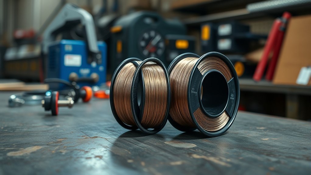
The obvious difference is wire diameter: .030 in. is about 0.8 mm, while .035 in. is about 0.9 mm. That small dimensional change affects how much wire is fed into the arc, but diameter alone does not determine heat input, penetration, or the maximum material thickness.
A smaller .030 wire is often useful where the machine and procedure call for lower output and finer puddle control. A .035 wire can carry more weld metal per unit length and may support a higher deposition rate when operated in the appropriate range.
Manufacturer data shows why generic rules can be misleading. For Lincoln Electric Innershield NR-211-MP, the published operating table lists .030 wire at about 13–19 arc volts and approximately 30–140 amps, while .035 is listed at about 14–21 arc volts and approximately 30–155 amps. The operating windows overlap substantially.
| Factor | .030 Flux Core | .035 Flux Core |
|---|---|---|
| Diameter | 0.030 in. / about 0.8 mm | 0.035 in. / about 0.9 mm |
| Typical reason to choose it | More control on lighter work or a lower-output machine when the procedure permits it | Higher deposition or output when the machine and procedure support it |
| Material range | Product- and machine-specific | Product- and machine-specific |
| Outdoor suitability | Depends on whether the electrode is self-shielded and approved for the application | Depends on whether the electrode is self-shielded and approved for the application |
Diameter is only one variable. The exact flux-core electrode, machine chart, joint, position, polarity, and required weld quality determine whether .030 or .035 is appropriate.
Do not use a rule such as “.030 needs 210V and .035 needs 250V.” Those numbers confuse input power with welding output. A compact welder can operate from a 120V branch circuit and still be designed for .035 self-shielded wire. The wire’s required arc voltage is normally far lower and must come from the specific welding procedure.
In practical terms, .030 often suits lighter work, while .035 may offer more productivity when the equipment can run it correctly. If you are comparing consumables, this guide to flux core welding wires can help with product-level choices after the required diameter and classification are known.
Check the Wire Classification Before Choosing Diameter
Before comparing .030 and .035, identify the exact wire. “Flux core” covers more than one type of electrode, and two wires with the same diameter may require different shielding, polarity, operating ranges, positions, or pass limits.
Self-shielded flux-cored arc welding, often written FCAW-S, creates its own shielding from the electrode’s flux ingredients and does not use an external shielding-gas cylinder. Gas-shielded flux core, or FCAW-G, uses external shielding gas and follows a different procedure.
Also check the AWS classification printed on the spool or data sheet. Common DIY self-shielded wires include classifications such as E71T-11 and E71T-GS, but the classification and manufacturer instructions—not diameter alone—tell you important limits such as allowable welding positions and whether the product is intended for single or multiple passes.
Note: Never copy voltage, wire-feed speed, polarity, or thickness limits from a different flux-core product simply because both wires are .030 or .035. Start with the label and data sheet for the exact spool you are using.
Choose Flux Core Wire for Thin Metal
For thin metal, .030 flux-cored wire is often the easier diameter to control when both the machine and electrode approve it. The smaller wire can allow useful lower-output operating points, helping the welder manage the puddle and reduce the chance of overheating light-gauge material.
That does not mean .030 has a universal “22 to 14 gauge” range. The minimum and maximum thickness depend on the wire, machine, joint design, travel speed, fit-up, position, and whether multiple passes are allowed.
A good example is Lincoln’s Weld-Pak 90i FC chart for NR-211-MP. Its published machine-specific table includes .030 settings across thinner gauges where the same machine does not list .035 at its lightest setting. That is useful guidance for that machine and electrode combination, not a universal thickness chart for every .030 wire.
On thin sheet, control burn-through by keeping good fit-up, using the manufacturer’s starting parameters, maintaining the recommended contact-tip-to-work distance, and moving steadily. Excessive heat, slow travel, or a large gap can burn through even when the selected wire diameter is otherwise appropriate.
The goal is a consistent bead with adequate fusion, not simply the lowest possible heat. A weld that looks neat but sits on the surface with poor fusion is not an acceptable trade for avoiding burn-through.
Solid MIG wire and self-shielded flux-core wire also behave differently, so do not transfer settings directly between them. If you are comparing consumable types, this guide to quality welding wire covers a separate wire category.
Match Flux Core Wire to Your Welder
Welder compatibility should be verified before changing between .030 and .035. Check more than the machine’s maximum amperage. The full wire-feeding system must support the diameter.
- Machine manual: Confirm that the power source lists the exact flux-core diameter.
- Output range: Make sure the machine can reach and sustain the voltage and wire-feed range required by the electrode.
- Duty cycle: A machine may make the weld but overheat if operated beyond its rated duty cycle.
- Drive roll: Flux-core wire commonly uses a knurled groove; install the groove and size specified by the machine manufacturer.
- Contact tip: Match the contact-tip size to the wire diameter.
- Gun, liner, and guides: Confirm that the entire feed path is suitable for the wire.
- Spool capacity: Verify that the package size fits the machine.
- Polarity: Follow the exact electrode and machine instructions rather than assuming polarity from diameter.
The Lincoln Weld-Pak 90i FC manual illustrates the difference between input power and wire compatibility. The machine uses a 120V input connection, while its FCAW setup information includes both .030 and .035 NR-211-MP, matching each diameter to the appropriate contact tip and a .030/.035 knurled drive-roll groove.
Compact machines such as the Handler 140 can also be designed around .030 and .035 flux-core wire, but the model-specific manual should always control the choice. Never assume that every 120V or 140-amp-class machine supports the same wire and thickness range.
Warning: Turn the welder off before changing drive rolls, guides, or contact tips. Welding involves electrical shock, arc radiation, hot metal, sparks, fire hazards, and hazardous fumes. Wear proper eye, face, hand, and body protection, remove combustible materials, and provide suitable ventilation or local exhaust. Follow the machine manual, electrode SDS, and applicable workplace requirements.
Do not infer flux-core capability from another welding process. If you are comparing equipment categories, this guide to TIG welders under $2,000 covers TIG equipment, which does not by itself establish FCAW wire compatibility.
Use .035 Flux Core Wire for Thicker Steel
When the machine and electrode support it, .035 flux core wire can be a strong choice for heavier fabrication because the larger wire can provide a higher weld-metal deposition rate at suitable settings.
However, .035 should not be described as a universal “20 gauge to 3/16 in.” wire. For example, Lincoln NR-211-MP lists a maximum plate thickness of 5/16 in. for both .030 and .035 diameters, while an individual compact machine may have a much lower usable limit. The limiting factor can be the power source, joint, welding position, pass restriction, or approved procedure rather than wire diameter.
Published NR-211-MP operating data also shows why .035 is often chosen for productivity. At the upper end of that specific product’s table, .035 has a higher listed deposition rate than .030. That does not mean every .035 wire automatically gives deeper penetration or a stronger weld; sufficient fusion still depends on voltage, current, wire-feed speed, travel speed, joint preparation, stickout, and technique.
| Factor | .035 Wire | Practical Effect |
|---|---|---|
| Heat input | Can operate at higher output when the procedure calls for it | Can help achieve adequate fusion on heavier joints |
| Weld metal | Potential for higher deposition | Faster build-up when machine capacity and procedure allow |
| Application | Often selected for medium or heavier fabrication | Useful when productivity and required weld size favor .035 |
Self-shielded flux core is popular outdoors because it does not rely on an external shielding-gas cloud. That benefit comes from the electrode design, not simply from choosing .035 instead of .030. Hobart, for example, describes its self-shielded Fabshield 23 as suitable for outdoor or drafty conditions and offers the product in multiple diameters.
For heavier work, equipment output becomes increasingly important. A suitable multi-process welder with the required power range may provide more headroom, but its manual still needs to approve the exact flux-core wire and procedure.
Dial In Settings for Better Welds
Choosing the correct wire diameter is only part of the setup. Voltage, wire-feed speed, polarity, contact-tip-to-work distance, travel speed, joint preparation, and welding position all affect weld quality.
Do not begin with generic values such as 210V for .030 or 250V for .035. Instead, use the settings chart inside the welder or the data sheet supplied for the exact electrode. Manufacturer values are starting points and may require adjustment within the approved operating range.
Lincoln’s NR-211-MP data illustrates how much the two sizes overlap:
| NR-211-MP Example | .030 in. | .035 in. |
|---|---|---|
| Published arc-voltage range | About 13–19 V | About 14–21 V |
| Published approximate current | About 30–140 A | About 30–155 A |
| Published deposition range | About 0.4–2.6 lb/hr | About 0.7–3.4 lb/hr |
These figures apply to that specific electrode and must not be copied to another brand or classification without verification.
A test bead on scrap material of the same type and similar thickness is useful for dialing in a noncritical practice or repair setup. Look at bead shape, fusion at the toes, spatter, slag behavior, and whether the arc feeds smoothly.
- Burn-through: Heat input may be too high, travel too slow, or fit-up too wide.
- High, rope-like bead or poor toe fusion: The weld may be too cold, travel may be too fast, or the procedure may not provide enough output.
- Undercut: Excessive voltage, poor torch angle, or excessive travel speed may contribute.
- Heavy spatter: Check voltage, wire-feed speed, polarity, stickout, contact tip, and wire feeding.
- Erratic feeding: Confirm the correct drive-roll groove, tension, liner/guide condition, tip size, and spool drag.
Miller notes that incorrect polarity, low voltage, or the wrong contact-tip setup can contribute to poor self-shielded flux-core performance. Follow the exact wire instructions and troubleshoot one variable at a time.
Pro Tip: When changing from .030 to .035, do not change only the spool. Confirm the contact tip, drive-roll groove, feeder path, polarity, machine chart, and wire-feed settings before striking an arc.
Well-matched equipment makes setup easier. When comparing machines, these well-made machines can provide useful shopping context, but the model manual remains the authority for wire compatibility.
For structural, load-bearing, pressure-containing, vehicle-safety, or code-governed work, a visually good scrap test is not enough. Use the required welding procedure specification, qualified consumables and parameters, and the inspection requirements applicable to the job.
Frequently Asked Questions
When should I use .030 vs .035 flux core wire?
Use .030 when the exact electrode and welder support it and you want good control on lighter work. Choose .035 when the machine and procedure favor its greater deposition potential or output range. Material thickness alone should not make the decision.
What size flux core wire is best?
There is no universal best size. Match the exact wire classification and diameter to the machine, joint, position, required weld size, material, allowable passes, duty cycle, and manufacturer procedure. For many small-shop jobs .030 is convenient, while .035 can offer more deposition when the equipment supports it.
What amperage is best for .035 flux core wire?
There is no single amperage range for every .035 flux-core wire. As one example, Lincoln NR-211-MP .035 has published operating points from about 30 to 155 amps. Another electrode may differ, so use its data sheet and your machine chart rather than a generic 130–200 amp rule.
How thick of metal can you weld with .035 flux core wire?
The maximum thickness depends on the exact electrode, machine, joint, position, and pass procedure. Lincoln lists a 5/16-inch maximum plate thickness for .035 NR-211-MP, but a small welder may be rated for substantially less. Use the lower limit imposed by the wire procedure or machine.
Can I put .035 flux core wire in a welder that came with .030?
Only if the welder manual approves .035 flux-core wire and the complete feed path supports it. You may need the correct .035 contact tip, drive-roll groove, liner or guides, spool setup, and new voltage and wire-feed settings.
Is .035 flux core wire better than .030 in windy conditions?
Not simply because it is larger. Outdoor performance is mainly determined by whether the electrode is designed to be self-shielded and by its manufacturer procedure. Both .030 and .035 versions of suitable self-shielded products may be used outdoors when their instructions permit it.
Conclusion
The choice between .030 and .035 flux core wire is a balance of control, machine capacity, electrode requirements, and deposition needs. .030 is often convenient for lighter work and lower-output setups, while .035 can provide more deposition when the welder and procedure support it. Avoid universal voltage, amperage, or thickness rules. Check the exact wire data sheet, machine chart, polarity, feeder hardware, and joint requirements before welding. A properly matched system produces more consistent fusion and fewer setup problems than choosing diameter by thickness alone.
Sources
- Lincoln Electric — Innershield NR-211-MP Data Sheet — operating voltage, amperage, deposition rate, classification, positions, and plate-thickness limits.
- Lincoln Electric — Weld-Pak 90i FC Operator’s Manual — 120V machine input, .030/.035 wire setup, contact tips, drive roll, and machine-specific settings.
- Hobart Brothers — Fabshield 23 — self-shielded flux-core use outdoors and in drafty conditions.
- Miller Electric — Troubleshooting Common Weld Defects — polarity, voltage, contact-tip, spatter, bead shape, and troubleshooting guidance.
- OSHA — Welding, Cutting, and Brazing Hazards and Solutions — welding fumes, UV exposure, burns, electrical hazards, and PPE.