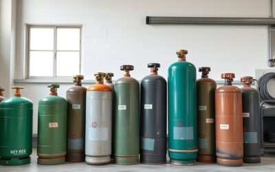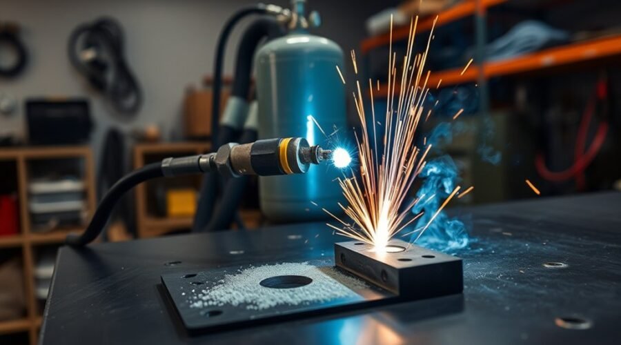
MIG welding with 100% CO2 is a practical option for carbon and mild steel when gas cost and penetration matter more than having the smoothest possible arc. Straight CO2 generally produces deeper penetration than C25, but it also creates more spatter and a rougher bead. Good results depend on using CO2-rated gas equipment, clean metal, the correct polarity, and settings matched to your wire, material thickness, joint, and welder.
Quick Answer
Yes, you can MIG weld mild steel with 100% CO2. It usually gives deeper penetration but more spatter and a harsher arc than 75/25 argon-CO2. Use a CO2-rated regulator or flowmeter, DCEP polarity with solid wire, proper ventilation, and your welder’s recommended C100 settings rather than relying on one universal voltage or wire-speed number.
Key Takeaways
- 100% CO2 is a proven shielding gas for MIG welding carbon and mild steel and generally provides deeper penetration than C25.
- Expect more spatter, a rougher arc, and more cleanup than with 75/25 argon-CO2.
- Do not use a universal “+1 to 2 volts” or “250 to 350 IPM” rule. Start with the chart for your welder, wire diameter, gas, and steel thickness.
- Use a regulator or flowmeter approved for CO2 service and the correct CGA-320 cylinder connection.
- For solid-wire mild-steel MIG, DCEP polarity and clean base metal are standard starting requirements.
- Remaining CO2 is best estimated by cylinder weight, not by watching for a particular pressure-gauge reading.
At a Glance
| Time Required | About 10–20 minutes for cylinder setup, leak checks, and test beads before starting the actual fabrication work |
| Difficulty | Beginner to intermediate; basic MIG setup and test-bead tuning are required |
| Tools Needed | Gas-capable MIG welder, CO2 cylinder, CO2-rated regulator/flowmeter, solid MIG wire, PPE, wire brush or grinder, and scrap steel for test beads |
| Cost | Varies by cylinder size, ownership or rental program, refill/exchange pricing, regulator, and local supplier |
Why Use 100% CO2 for MIG Welding?
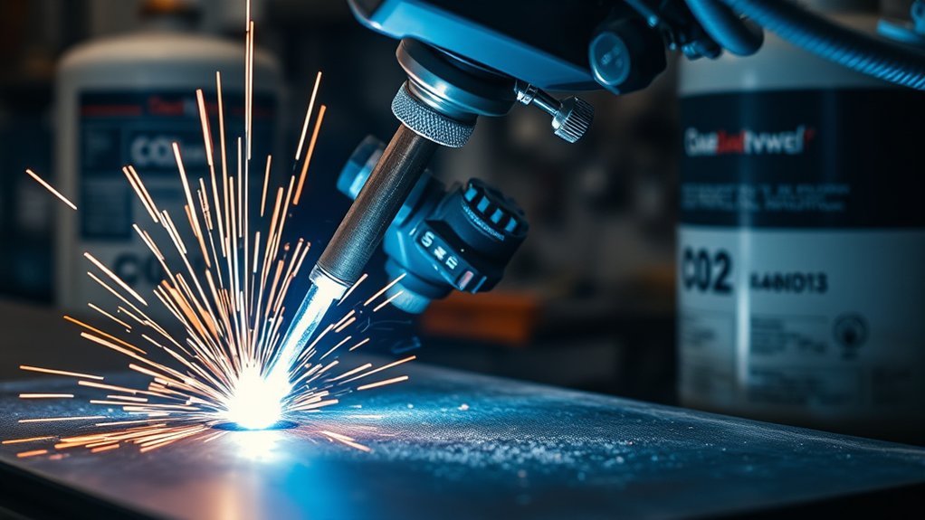
100% CO2 is widely used as a shielding gas for MIG welding carbon and mild steel. Its biggest advantages are strong penetration and the possibility of lower shielding-gas cost compared with argon-containing blends. Hobart Brothers notes that straight CO2 provides broad, deep joint penetration, while its main disadvantages are a less stable arc and more spatter.
That makes CO2 useful on thicker steel, repair work, general fabrication, and jobs where bead appearance is less important than fusion and economy. It is not automatically the best gas for every job. On thin sheet, the more energetic arc can make heat control and cleanup harder.
CO2 should also not be treated as permission to weld contaminated steel. Solid MIG wire performs best when rust, oil, paint, heavy mill scale, and other contamination are removed. Miller recommends cleaning the work to bare metal where practical and making sure the work clamp contacts clean metal.
If bead appearance and easier tuning are priorities, a 75/25 argon-CO2 blend, commonly called C25, is often the easier all-purpose choice for mild steel.
MIG Welding With CO2 vs C25
Both straight CO2 and C25 can work well on mild steel, but they produce noticeably different arc behavior. CO2 generally gives greater penetration and more spatter. C25 generally gives a smoother arc, less cleanup, and a more attractive bead.
| Factor | 100% CO2 | C25 — 75% Argon / 25% CO2 |
|---|---|---|
| Penetration | Generally deeper | Moderate and easier to control on thinner steel |
| Spatter | Higher | Lower |
| Arc feel | More forceful and less smooth | Smoother and more forgiving |
| Bead appearance | Rougher, with more cleanup | Usually cleaner |
| Thin sheet | Requires more careful heat control | Usually easier to manage |
| Gas cost | Often lower, depending on local supplier | Often higher because it contains argon |
CO2 Penetration and Spatter
When used on mild steel, 100% CO2 commonly produces deeper joint penetration than C25. This can be useful on thicker material where adequate fusion is important.
The tradeoff is greater spatter production. Straight CO2 also tends to have rougher droplet transfer than argon-rich mixtures. More spatter means more time spent cleaning the nozzle, workpiece, fixtures, and finished weld.
Do not assume that every CO2 setup needs exactly 1 to 2 additional volts. Voltage and wire-feed speed interact, and the correct combination depends on the wire diameter, steel thickness, joint design, position, contact-tip-to-work distance, and individual welder.
Pro Tip: If your welder has separate C25 and C100 charts or synergic modes, use the C100 values first. Make a test bead on matching scrap, then change one setting at a time and record what works.
C25 Smooth Arc Control
C25 is often preferred when a smoother and more forgiving MIG arc is needed. It is especially useful on lighter-gauge steel or jobs where bead appearance matters.
Lincoln Electric’s shielding-gas guidance lists 75% argon/25% CO2 as a common short-circuit blend that reduces spatter and improves bead appearance on carbon steel.
C25 generally gives a smoother puddle, easier starts, and less cleanup than straight CO2. That can make it a better match for body panels, thin tubing, decorative fabrication, and general-purpose shop welding.
Choosing the correct shielding gas is only one part of good MIG welder performance; machine output range and parameter control also matter.
Cost and Tank Differences
Cost often favors straight CO2, but exact prices should be checked locally. Cylinder purchase prices, rental agreements, deposits, exchanges, refill charges, and available sizes vary by supplier and region.
A useful comparison is to ask the same supplier for the current total cost of obtaining and refilling the amount of CO2 and C25 you actually expect to use. Do not compare one cylinder only by its advertised physical size because CO2 cylinders are commonly sold by pounds of product while shielding-gas mixes are often described by cubic-foot capacity.
Portability also depends on the specific cylinder. A small CO2 bottle may be easy to transport, but straight CO2 is not automatically lighter than every comparable C25 setup.
What You Need for CO2 MIG Welding
A reliable CO2 MIG setup needs a gas-capable welder, the correct wire and polarity, a CO2 cylinder, suitable gas-control equipment, clean base metal, and normal welding PPE.
CO2-Compatible MIG Gear
For solid-wire mild-steel MIG, a typical setup includes:
- A MIG welder capable of gas-shielded GMAW.
- A cylinder containing welding-grade CO2.
- A regulator or flowmeter specifically approved for CO2 service.
- The correct cylinder connection, commonly CGA-320 in the United States.
- Solid mild-steel wire such as ER70S-6 in a diameter supported by the machine.
- DCEP polarity for common solid-wire mild-steel MIG.
- A sound contact tip, liner, nozzle, drive rolls, gun cable, and work lead.
- Welding helmet, safety glasses, gloves, flame-resistant clothing, and adequate ventilation.
For long jobs, a machine with good duty cycle and stable wire delivery matters more than marketing language about a particular power technology. A capable multi-process welder can also be useful if its MIG mode explicitly supports straight CO2.
Gas-shielded flux-cored wire is a different process from solid-wire MIG and may require a specific shielding-gas blend. If you use dual-shield wire, follow the wire manufacturer’s classification and gas recommendation rather than assuming the same CO2 settings will apply. The same rule applies when comparing different flux-core welding wires.
Regulator and Adapter Needs
The simplest setup is a regulator or flowmeter that is explicitly rated for carbon dioxide service and connects directly to the CO2 cylinder.
For example, commercial CO2 welding regulators commonly use a CGA-320 inlet. A separate adapter is therefore not automatically required. ESAB lists dedicated CO2 versions of its flowmeter regulator with a CO2 connection.
Do not assume that an argon flowmeter becomes suitable for straight CO2 simply because an adapter physically fits. Flow tubes can be calibrated for specific gases, and seals, pressure ranges, fittings, or duty ratings may differ. Use the regulator manufacturer’s approved configuration.
Note: CO2 is stored as liquefied gas in the cylinder. Cylinder pressure changes strongly with temperature and does not provide a reliable “fuel gauge” while liquid CO2 remains. Weighing the cylinder and subtracting its tare weight is the better way to estimate remaining contents.
How to Set Up a MIG Welder for 100% CO2
- Confirm the machine supports gas-shielded MIG. Check the owner’s manual for straight CO2 or C100 compatibility.
- Secure the cylinder upright. Use a chain, strap, or approved cylinder cart so it cannot fall.
- Install the correct regulator or flowmeter. Use CO2-rated equipment with the correct cylinder connection and inspect the fitting before tightening it.
- Connect the shielding-gas hose. Inspect hoses for cracking, damage, or loose fittings.
- Load the correct wire. ER70S-6 is a common mild-steel solid wire because its deoxidizers help tolerate normal mill conditions, although the steel should still be cleaned.
- Set polarity. Common solid-wire mild-steel MIG uses DCEP. Confirm the requirement on the wire label and welder chart.
- Clean the joint and work-clamp area. Remove paint, oil, rust, heavy scale, and other contamination where practical.
- Turn on the gas and set flow. A common indoor MIG starting range is around 20 to 25 CFH, although the correct value depends on nozzle size, machine guidance, drafts, and the process.
- Choose the machine’s C100 starting settings. Select values based on material thickness and wire diameter instead of using one fixed voltage/WFS rule.
- Make a test bead on matching scrap. Inspect arc behavior, spatter, bead shape, fusion, and penetration before welding the actual part.
Warning: Welding creates hazardous fumes and gases, and CO2 can accumulate in poorly ventilated areas. Use adequate general or local exhaust ventilation, wear appropriate PPE, keep cylinders secured, and do not weld in a confined space without the controls required for that environment. OSHA requires welding ventilation sufficient to keep airborne contamination within applicable limits.
Which Metals Can You MIG Weld With 100% CO2?
The guidance in this article is mainly for carbon and mild steel. Straight CO2 should not be treated as a universal MIG shielding gas.
- Mild/carbon steel: 100% CO2 is a common and technically valid choice with suitable solid wire and machine settings.
- Stainless steel: Straight CO2 is generally not the preferred choice. Stainless procedures commonly use argon-rich blends with small controlled additions of CO2 or oxygen. Follow the wire manufacturer’s approved gas.
- Aluminum: Do not substitute straight CO2 for the normal aluminum MIG shielding gas. Aluminum MIG commonly uses 100% argon or another manufacturer-approved inert-gas procedure.
Lincoln Electric’s GMAW shielding-gas guide shows how gas selection changes with base metal, electrode, and transfer mode.
How Pure CO2 Changes the Arc
Pure carbon dioxide produces a more forceful and less smooth MIG arc than common argon-CO2 blends. With solid wire, straight CO2 is commonly used in short-circuit applications and can move toward globular transfer as current rises.
Argon-rich gas mixtures are normally used when a procedure requires stable axial spray transfer. This is one reason a gas change can alter more than bead appearance: shielding gas affects arc voltage, transfer behavior, penetration profile, spatter, and operating range.
- The arc usually feels harsher than C25.
- Droplet transfer tends to produce more spatter.
- Penetration is generally deeper.
- Voltage and WFS must be balanced for the actual machine and joint.
- Thin sheet is more sensitive to burn-through and distortion.
If your machine has inductance control, follow its manual. On many short-circuit systems, inductance changes how quickly welding current rises during a short circuit and can alter arc softness and wetting. The useful setting is machine-specific.
For a new operator, a machine designed around simple parameter charts or synergic modes can make gas changes easier. That is one reason setup controls matter when choosing among welders for beginners.
Best Settings for CO2 MIG Welding
There is no single set of “best” CO2 MIG settings. The correct values depend on steel thickness, joint design, wire diameter, welding position, machine output, stickout, and travel speed.
Miller recommends starting with the parameter chart on the welder and matching the setup to material thickness and wire size.
| Parameter | Starting Guidance | What to Watch |
|---|---|---|
| Voltage | Use the machine’s C100 chart for your wire and steel thickness | Too low relative to WFS can produce harsh stubbing and spatter; too high can create an overly long arc or undercut |
| Wire-feed speed | Match it to wire diameter and required current/deposition | Excess WFS for the voltage causes stubbing; too little can create an unstable long arc |
| Gas flow | About 20–25 CFH is a common indoor starting point; follow the machine and regulator guidance | Too little shielding can cause porosity; excessive flow wastes gas and can create turbulence |
| Polarity | DCEP for common solid mild-steel MIG wire | Wrong polarity can cause poor arc behavior and penetration |
| Travel speed | Steady enough to maintain the intended bead size and fusion | Too slow increases heat input; too fast can reduce fusion and leave a narrow bead |
The useful method is to make a bead on scrap of the same thickness, change one variable at a time, and inspect the result. This is more reliable than copying a generic voltage and IPM number from another welder.
How to Reduce Spatter With CO2
You cannot make straight CO2 behave exactly like an argon-rich blend, but you can reduce unnecessary spatter by keeping the entire setup in balance.
- Clean the steel. Rust, mill scale, paint, and oil can increase instability, porosity, and cleanup.
- Confirm polarity. Use the wire manufacturer’s required polarity.
- Balance voltage and WFS. Do not simply lower both. Hobart notes that voltage that is too low relative to WFS is a common contributor to excessive spatter.
- Keep the nozzle and contact tip clean. Heavy spatter buildup can disturb shielding and wire delivery.
- Use a steady travel speed and gun angle. Large changes in gun position make the puddle harder to control.
- Check wire feeding. Incorrect drive-roll pressure, a damaged liner, worn tip, or tangled spool can create an erratic arc.
- Protect the gas envelope. Drafts can pull shielding gas away from the weld even when the flowmeter shows a normal value.
If you have tuned the machine carefully and still need substantially less spatter or a cleaner cosmetic bead, switching from straight CO2 to C25 may be more effective than continuing to chase settings.
Owners of combination machines should also remember that settings which work in MIG mode do not transfer directly to other processes. This applies even when comparing features found on multi-process TIG-capable machines.
CO2 MIG Welding Troubleshooting
| Problem | Likely Causes | What to Check |
|---|---|---|
| Excess spatter | Normal CO2 behavior, voltage/WFS mismatch, dirty metal, poor wire feed | Clean steel, confirm polarity, retune voltage against WFS, inspect tip/liner/drive rolls |
| Porosity | Low gas flow, leaks, drafts, contamination, clogged nozzle | Leak-test hoses, clean nozzle and joint, shield the work from drafts, verify flow while gas is actually flowing |
| Burn-through | Too much heat for thin steel, slow travel, large wire, excessive gap | Reduce heat input using the machine chart, move faster, use smaller wire if appropriate, or consider C25 for thin sheet |
| Lack of fusion | Too little heat, fast travel, poor joint preparation, contamination | Verify chart settings, clean and bevel thick joints as required, and confirm the arc reaches both joint faces |
| Wire stubbing | WFS too high for voltage, poor feeding, incorrect tip | Increase voltage within the proper range or reduce WFS, then inspect drive system and contact tip |
| Regulator frosting or flow drop | High sustained CO2 withdrawal and expansion cooling | Use equipment rated for the required CO2 flow and duty; do not heat a cylinder or regulator with an improvised flame or unsafe heat source |
CO2 Penetration, Speed, and Cleanup
MIG welding with 100% CO2 is known for deep joint penetration compared with C25 under comparable mild-steel conditions. That can be useful on thicker work, but it does not mean straight CO2 automatically produces higher travel speed or greater production output in every procedure.
Throughput depends on wire diameter, WFS, current, joint design, position, required weld size, duty cycle, operator technique, and acceptance criteria. The shielding gas is only one part of the procedure.
Straight CO2 can give deeper penetration, but the productive setting is the one that achieves the required fusion and bead profile without excessive spatter, porosity, undercut, or rework.
Cleanup is one of CO2’s main tradeoffs. More spatter can increase grinding, brushing, anti-spatter maintenance, and nozzle cleaning. Those labor costs should be included when comparing CO2 with C25 rather than looking only at the price of the gas.
The same principle applies when comparing another arc-welding process. Features discussed in stick-welder arc control should not be assumed to behave the same way as MIG voltage, WFS, or inductance controls.
CO2 Tank Sizes, Refills, and Cost
CO2 cylinders are commonly described by the weight of carbon dioxide they hold. A 20-pound cylinder is a familiar shop size, but smaller and larger options may be available from local welding-gas suppliers.
Air Products lists approximately 8.743 cubic feet of CO2 gas per pound at 70°F and one atmosphere. On that basis, a nominal 20-pound CO2 fill corresponds to about 175 cubic feet of gas under those reference conditions.
At a continuous 20 CFH flow, 175 cubic feet represents roughly 8.7 hours of theoretical gas-flow time. Actual shop usage varies because of flow setting, pre-flow or post-flow, leaks, purging, fitting changes, and the fact that the welder is not continuously arcing.
Do not use cylinder pressure as the main gauge of how many pounds of liquid CO2 remain. The more useful method is:
- Find the cylinder’s stamped tare weight.
- Weigh the cylinder with its normal valve installed.
- Subtract the tare weight from the measured weight.
- The difference gives an approximate remaining CO2 mass.
Refill and exchange prices change by region, cylinder ownership, supplier, and quantity. Obtain current quotes instead of assuming an old fixed price. When comparing machines intended for a garage or hobby shop, cylinder storage and supplier access are worth considering alongside the capabilities covered in guides to welders for home use.
CO2 Cylinder and Welding Safety
CO2 is nonflammable, but that does not make it harmless. It can displace breathable air, and welding itself creates fumes, ultraviolet radiation, hot metal, sparks, and electrical hazards.
OSHA’s welding requirements address ventilation and personal protection for welding operations. For practical shop use:
- Keep the cylinder secured so it cannot fall.
- Protect the cylinder and regulator from impact and excessive heat.
- Close the cylinder valve when the system is not in use.
- Use adequate ventilation and local fume extraction where needed.
- Never depend on smell to detect an unsafe gas buildup.
- Do not weld in a confined or poorly ventilated space without the required atmospheric controls and procedures.
- Wear a welding helmet with the appropriate filter shade, safety glasses, gloves, flame-resistant clothing, and suitable footwear.
- Keep combustible materials away from sparks and hot metal.
- Check the welder, leads, gun, hoses, regulator, and fittings before use.
When Pure CO2 Is the Best Choice
| Situation | 100% CO2 | Why |
|---|---|---|
| Thicker mild steel | Good choice | Strong penetration can be useful when the procedure is set correctly |
| Lowest possible gas cost | Often favorable | Straight CO2 is commonly less expensive than argon-containing blends, although local prices vary |
| Cosmetic welds | Usually not first choice | C25 generally produces less spatter and a smoother-looking bead |
| Thin automotive sheet | Usable with careful setup | C25 is often easier to control and less prone to excessive spatter |
| Aluminum | No | Use the inert shielding gas specified for aluminum MIG, commonly argon |
| Stainless steel | Generally not preferred | Use the wire manufacturer’s approved stainless shielding-gas blend |
Pure CO2 makes the most sense when you are welding compatible steel, your machine supports it, penetration is useful, and you accept additional spatter and cleanup in exchange for the potential gas-cost advantage.
Small MIG machines can also run differently at the edge of their output range, so gas choice should be considered together with machine capacity. That matters when comparing compact units such as those discussed in the Hobart Handler 140 vs Lincoln 140 comparison.
Frequently Asked Questions
Can I MIG weld with 100% CO2?
Yes. Straight CO2 is a valid shielding gas for MIG welding carbon and mild steel when the machine, regulator, wire, polarity, and welding parameters are suitable. Expect deeper penetration and more spatter than with C25.
What are good MIG settings for 100% CO2?
Start with the C100 chart in your welder’s manual or door chart for the actual wire diameter and steel thickness. There is no universal voltage or IPM setting. Make a test bead on matching scrap and balance voltage with wire-feed speed until the arc is stable and the bead has the required fusion and profile.
Can you MIG weld with 100% oxygen?
No. Pure oxygen is not an appropriate MIG shielding gas. It would aggressively oxidize the molten weld and greatly increase combustion hazards. Use the shielding gas specified for the metal, wire, and transfer mode.
What is the best gas to use when MIG welding?
For general mild-steel short-circuit MIG, C25 is a popular all-purpose choice because it gives a smooth arc, relatively low spatter, and good bead appearance. Straight CO2 is useful when deeper penetration and lower gas cost are more important. Other metals and transfer modes require different shielding gases.
Can I use 100% CO2 to MIG weld aluminum or stainless steel?
Do not use straight CO2 as a general aluminum MIG shielding gas; aluminum commonly uses argon. Straight CO2 is also generally not the preferred gas for stainless steel. Use the shielding gas approved by the filler-wire and equipment manufacturer for those metals.
How do I know how much CO2 is left in the cylinder?
Use weight rather than relying on cylinder pressure. Weigh the cylinder and subtract its stamped tare weight. CO2 is stored partly as liquid, so pressure is strongly affected by temperature and does not fall in direct proportion to the amount of CO2 remaining while liquid is still present.
Sources
- MillerWelds — Understanding the Basics of MIG Welding for Mild Steel — wire choice, polarity, surface preparation, gas flow, and CO2 vs C25 guidance.
- Hobart Brothers — Welding Shielding Gas and Weld Performance — straight CO2 penetration, arc stability, and spatter characteristics.
- Lincoln Electric — GMAW Shielding Gas Selection Guide — shielding gases by material and transfer mode.
- ESAB — GRF400 Flowmeter Regulator — CO2-rated gas-regulator configurations.
- OSHA — Welding, Cutting, and Brazing General Requirements — ventilation and personal-protection requirements.
- Air Products — Carbon Dioxide Weight and Volume Equivalents — CO2 mass-to-gas-volume conversion.
Conclusion
MIG welding with 100% CO2 is a practical option for carbon and mild steel when strong penetration and potentially lower shielding-gas cost matter more than having the smoothest arc or cleanest bead. Its main tradeoffs are more spatter, a harsher arc, and extra cleanup compared with C25. Use CO2-rated gas equipment, DCEP with appropriate solid wire, clean steel, adequate ventilation, and the settings recommended for your actual welder and material. For thin sheet or work where bead appearance and easy arc control matter most, C25 is usually the more forgiving choice.