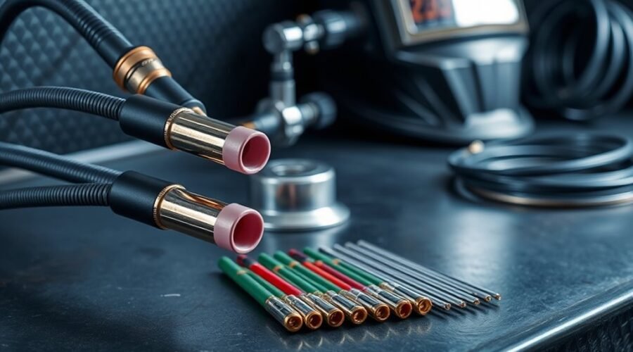
Choosing TIG welding equipment starts with matching the torch, tungsten electrode, shielding setup, and power source to the amperage and duty cycle you actually use. A compact air-cooled torch works well for many repair and fabrication jobs, while sustained high-amperage TIG often benefits from a water-cooled torch. Tungsten diameter, alloy, cup size, gas flow, and stickout also need to work together for a stable arc and clean shielding.
Quick Answer
Choose a TIG torch by its actual amperage rating, duty cycle, cooling method, and compatibility with your welder—not by torch-series number alone. For modern inverter TIG machines, 2% lanthanated or ceriated tungsten is a practical starting choice. Set argon flow to the lowest rate that provides complete shielding, then adjust cup size and tungsten stickout to the joint.
Key Takeaways
- Choose the torch by its rated amperage, duty cycle, cooling method, physical size, and connection requirements.
- WP-17, WP-18, and WP-26 numbers are model families, not a low-to-high performance ranking.
- Match tungsten diameter to welding current, polarity, tungsten alloy, and power-source recommendations rather than material type alone.
- For many modern inverter machines, lanthanated or ceriated tungsten is a practical non-radioactive starting choice.
- Typical argon flow may fall around 10–25 CFH, but cup size, gas lens, joint geometry, drafts, and torch angle can require adjustment.
- Keep torch parts clean, grind tungsten lengthwise, check for gas leaks, and verify water flow before using a water-cooled torch.
At a Glance
| Time Required | About 10–20 minutes for initial torch assembly, gas checks, and tungsten preparation |
| Difficulty | Beginner to intermediate |
| Tools Needed | Compatible TIG torch, tungsten, collet, collet body or gas lens, cup, argon regulator/flowmeter, dedicated tungsten grinder, and welding PPE |
| Cost | Varies by torch, consumables, and whether a water cooler is required; setup itself has no fixed additional cost |
Warning: TIG welding exposes the operator to electric shock, intense ultraviolet and infrared radiation, hot metal, fire hazards, and welding fumes or gases. Wear appropriate welding PPE, keep combustibles away, use adequate ventilation, and never rely on shielding gas as breathable air. Confined-space welding requires additional ventilation and safety controls. Follow your welder and torch manufacturers’ manuals and applicable workplace rules.
How to Choose a TIG Torch
Start with the torch’s rated amperage and duty cycle. Duty cycle is the percentage of a 10-minute period that the torch can operate at its rated load without exceeding its thermal rating. A torch rated at 60% duty cycle, for example, is designed for six minutes of welding at its stated load followed by sufficient cooling time under the manufacturer’s test conditions.
Cooling method is equally important. An air-cooled TIG torch is simple, portable, and does not require a separate cooler, making it useful for field repair, hobby work, and intermittent fabrication. The tradeoff is that the torch body and cable become hotter as amperage and arc-on time increase.
A water-cooled TIG torch circulates coolant through the torch and cable. It is normally preferred for high-amperage work, long welds, production welding, or situations where a smaller torch body is desired at substantial current. It requires a compatible cooler, coolant hoses, proper coolant, and regular leak and flow checks.
Ergonomic grips, flexible necks, cable length, back-cap length, and torch-head size also affect access and operator fatigue. Before buying a torch, confirm the power connection, gas connection, remote-switch arrangement if used, cooler requirements, and consumable family.
If you are also selecting a TIG power source, compare the machine’s maximum output and AC/DC capability with the torch you intend to use. This existing guide to AC/DC TIG welder options can help when matching the power source to the work.
TIG torch numbers are model families, not a performance ranking. Always compare the manufacturer’s amperage rating, duty cycle, and cooling method.
TIG Torch Sizes and Amperage
WP-17, WP-18, and WP-26 style torches are common, but the model number alone does not tell you which torch carries the most current. Current Weldcraft specifications illustrate why the actual rating matters.
| Torch family | Cooling | Typical Weldcraft rating | Typical use |
|---|---|---|---|
| WP-17 / A-150 | Air-cooled | 150 A DC / 115 A AC at 60% duty cycle | General fabrication, repair, portable work |
| WP-26 / A-200 | Air-cooled | 200 A DC / 150 A AC at 60% duty cycle | Higher-current air-cooled work |
| WP-18 / W-350 | Water-cooled | 350 A DC / 250 A AC at 100% duty cycle | High-amperage and sustained welding |
These ratings are manufacturer-specific examples, so check the specification for your exact torch. Miller’s Weldcraft TIG torch specifications provide rated output, cooling type, electrode range, and duty cycle for its torch families.
The torch must also be sized to the machine. Installing a 200-amp torch does not make a 150-amp welder produce more current, and running a torch beyond its rated load or duty cycle can overheat cables, seals, handles, and consumables.
If you are comparing machines as well as torches, this existing guide to TIG welder power ranges and controls can help put the torch rating in context.
When to Use a Gas Lens?
A gas lens replaces the standard collet-body gas outlets with fine screens that straighten shielding-gas flow. This produces a smoother, more uniform gas column and can improve shielding around the tungsten and weld pool.
A gas lens is especially useful when welding stainless steel, titanium, nickel alloys, open-root joints, outside corners, or other work where shielding quality and access are important. It can also permit greater tungsten extension than a conventional collet body, making it easier to reach into tight joints while maintaining gas coverage.
- Use a gas lens when you need additional tungsten stickout for access.
- Use one when weld color and oxidation control are especially important.
- Consider a larger cup when the weld zone needs broader shielding coverage.
- Use a standard collet body when compact size or simple, non-critical work makes it more practical.
Miller notes that a conventional collet-body setup should generally keep tungsten extension within the inside diameter of the nozzle, while a gas lens permits a longer extension because of its smoother gas flow. See Miller’s TIG shielding-gas guidance for additional details.
Pro Tip: More argon is not automatically better. Excessive flow can become turbulent and draw surrounding air into the shielding envelope. Use the lowest flow that produces clean, complete coverage for your cup, joint, and working conditions.
Gas lenses can improve consistency, but they do not automatically guarantee better welds or lower gas consumption. Torch angle, cup size, drafts, joint geometry, cleanliness, and gas-flow setting still matter. If you are evaluating TIG machines at different price levels, this existing guide to budget TIG welder options provides additional equipment context.
How to Pick the Right Tungsten
Choose tungsten by electrode alloy, diameter, welding current, polarity, and power-source design. Material type matters because it affects whether you weld with AC or DC, but stainless steel or titanium does not automatically require a larger electrode.
For many modern inverter TIG machines, 2% lanthanated (blue) and 2% ceriated (gray) tungsten are practical non-radioactive choices. Miller recommends ceriated and lanthanated electrodes for many inverter applications, while CK Worldwide identifies 2% lanthanated tungsten as a versatile option for AC and DC work.
| Tungsten size | Typical starting range on modern inverter equipment | General use |
|---|---|---|
| 1/16 in. (1.6 mm) | About 70–150 A | Lower-current and thinner-material work |
| 3/32 in. (2.4 mm) | About 150–200 A DCEN; usable range varies by machine and alloy | Versatile general-purpose size |
| 1/8 in. (3.2 mm) | Higher-current work | Heavy-current applications where the machine and torch support it |
These are starting ranges, not universal limits. Miller’s inverter guidance lists different ranges for AC and DCEN and recommends following the equipment manufacturer’s tungsten chart. See Miller’s tungsten selection guide for current selection and preparation guidance.
2% thoriated tungsten (red) can provide stable DC arc performance, but it contains thorium, a radioactive material. Where practical, non-thoriated alternatives such as lanthanated or ceriated tungsten avoid that issue. The IAEA guidance for thoriated tungsten recommends non-thoriated electrodes where practicable and additional controls when grinding thoriated electrodes.
Warning: Grinding thoriated tungsten can create radioactive dust. If thoriated electrodes are used, follow the electrode manufacturer’s SDS and applicable workplace rules, use local dust extraction or other specified controls, and keep the grinding area and equipment appropriately managed. A non-thoriated tungsten eliminates this particular thorium-dust concern.
Whatever alloy you use, grind a pointed tungsten lengthwise, not around its circumference. Use a dedicated tungsten grinder or a clean grinding wheel reserved for tungsten so other metals do not contaminate the electrode.
Welding gloves also affect fine torch and filler control. This existing guide to TIG welding gloves discusses options intended to preserve dexterity while protecting the hands.
How to Set Up Your TIG Torch
A reliable TIG setup follows a simple sequence: confirm compatibility, assemble the consumables, prepare the tungsten, set its extension, connect gas and cooling, inspect the torch, and verify shielding before welding.
1. Confirm Torch and Machine Compatibility
Check the torch’s rated amperage and duty cycle against the welder’s output. Verify the power connector or Dinse adapter, gas connection, torch switch or remote-control connection if used, and water-cooler requirements. Never run a water-cooled torch that requires coolant circulation without the cooler operating correctly.
2. Install the Correct Collet and Collet Body or Gas Lens
The collet and collet body or gas lens must match the tungsten diameter and torch family. Install the heat shield, collet body or gas lens, collet, cup, tungsten, and back cap according to the torch manufacturer’s parts diagram.
3. Prepare and Install the Tungsten
For pointed electrodes, grind lengthwise on a dedicated tungsten grinding surface. Install the tungsten without touching the prepared end with dirty gloves or oily hands. Tighten the back cap enough to hold the electrode securely without damaging the collet.
4. Set Tungsten Stickout
For a conventional collet body, a 1/8- to 1/4-inch extension is a useful starting point on many setups, and the electrode should normally remain within the inside diameter of the cup. A gas lens can support additional stickout when access requires it, provided shielding remains effective.
Stickout is not the same as arc length. During welding, Miller recommends keeping the tungsten close to the work—commonly around 1/16 to 1/8 inch where practical—without touching the puddle or filler.
5. Set Shielding Gas Flow
Pure argon is the standard shielding gas for most TIG welding. A flowmeter is preferable because it shows actual gas flow in CFH. A common starting range is roughly 10–25 CFH, with 15–20 CFH often working well for ordinary shop conditions.
Larger cups, long tungsten extension, difficult joint geometry, or minor air movement may require more flow. Excessive flow can create turbulence, however, so increase it only when necessary. Miller’s broader TIG guidance notes that applications can fall outside this range depending on consumables and atmospheric conditions.
6. Inspect Gas, Power, and Cooling Connections
- Check the gas hose, torch fittings, and regulator connection for leaks.
- Inspect the torch cable and power connection for damage, exposed conductors, or overheating.
- On a water-cooled torch, verify coolant level, flow, hose routing, and leak-free connections.
- Confirm the ceramic cup is not cracked and the gas lens screens are clean and undamaged.
7. Clean the Workpiece and Filler
Remove oil, grease, moisture, paint, rust, and other contamination using a cleaning method appropriate for the metal. Keep filler rod clean as well. Aluminum normally requires removal of its oxide layer with tools and procedures suitable for aluminum.
8. Make a Test Weld
Use a clean test coupon of similar material and thickness to confirm arc starting, amperage control, shielding, cup size, and gas flow before committing to the finished part.
Note: TIG commonly uses argon, while MIG shielding-gas requirements can be very different. If you use both processes, this existing MIG shielding gas guide covers those separate gas choices.
Which TIG Torch Parts Fit Your Job?
Selecting the right TIG torch parts starts with identifying the exact torch family. Consumables that fit a WP-17, WP-18, or WP-26 style front end may share some dimensions, but compact torches and other series can use different parts.
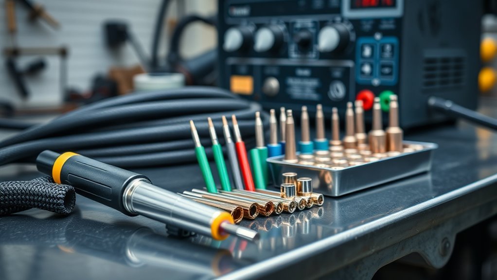
A basic TIG front end normally includes:
- Heat shield: insulates the front of the torch and supports the consumable stack.
- Collet: grips the tungsten when the back cap is tightened.
- Collet body or gas lens: holds the collet and directs shielding gas.
- Ceramic cup/nozzle: shapes and directs the shielding envelope.
- Back cap: secures the tungsten and is available in different lengths for clearance.
- Tungsten electrode: provides the non-consumable electrode that carries the arc.
Choose cup diameter according to access and shielding needs. A smaller cup can fit restricted joints, while a larger cup provides broader gas coverage. When using large cups or unusually long tungsten extension, adjust gas flow carefully and verify the result on a test piece rather than simply increasing CFH.
For stainless steel, titanium, nickel alloys, and other oxidation-sensitive work, a gas lens and adequate post-flow can help protect the hot tungsten and weld zone after the arc stops.
If the TIG process is part of a combination machine, also verify the machine’s TIG output, duty cycle, gas connections, and torch compatibility. This existing guide to multi-process welder duty cycles and capabilities provides additional machine-selection context.
TIG Welding Safety Before You Start
TIG often produces less visible smoke than processes such as flux-cored welding, but that does not make it hazard-free. The arc produces intense ultraviolet and infrared radiation, live electrical components can cause shock, hot metal can cause burns or fires, and shielding gas can displace breathable air.
The U.S. Occupational Safety and Health Administration requires appropriate PPE for welding and specifies ventilation requirements for welding under relevant workplace conditions. Review OSHA 29 CFR 1910.252 along with your equipment manual and applicable local rules.
- Wear a properly selected welding helmet, safety glasses, flame-resistant clothing, gloves, and suitable footwear.
- Keep the work area dry and inspect cables before use.
- Remove or protect combustible materials and keep appropriate fire-control equipment available.
- Use ventilation that keeps fumes and gases out of your breathing zone.
- Do not weld in tanks, vessels, or other confined spaces without the required confined-space procedures and ventilation.
- Secure compressed-gas cylinders upright and protect them from heat, impact, and electrical circuits.
Fix Common TIG Setup Problems
Most TIG setup problems can be traced to shielding, contamination, incorrect polarity, excessive current, unsuitable tungsten, damaged consumables, or overheating. Work through the checks below systematically instead of changing several variables at once.
Check Gas Flow
If the weld turns gray, black, sugary, porous, or heavily discolored, inspect shielding first. Start with the flowmeter and verify that gas is actually reaching the torch.
- Use a reasonable starting flow, often around 15–20 CFH for an ordinary cup in still indoor air.
- Inspect hoses and fittings for leaks.
- Check the cup for cracks.
- Inspect gas-lens screens for contamination or physical damage.
- Keep fans and strong drafts away from the shielding envelope.
- Reduce flow if excessive CFH is creating turbulence.
Miller specifically warns that excessive flow can create turbulence and pull surrounding atmosphere into the shielding-gas column.
Match Tungsten Size
The tungsten must carry the selected current without overheating while still providing reliable arc starts. If the tungsten tip rapidly balls, melts, splits, or erodes on DC welding, check amperage, polarity, tungsten diameter, tungsten alloy, and gas coverage.
Do not choose diameter from material thickness alone. Current range and power-source recommendations are better guides. A 3/32-inch electrode is a versatile general-purpose size for many TIG machines, while smaller electrodes can improve very-low-amperage starting and larger electrodes can handle greater current.
Clean Torch Components
A clean torch assembly supports stable gas flow and repeatable arc behavior. Inspect the collet, collet body or gas lens, cup, heat shield, back cap, and seals regularly.
- Replace cracked cups and damaged gas-lens screens.
- Replace worn collets that no longer grip the tungsten securely.
- Remove dust and debris that could restrict gas flow.
- Confirm each consumable is fully seated and compatible with the torch.
If the tungsten is contaminated, remove the contaminated section if necessary and regrind it on a dedicated tungsten grinder or clean grinding wheel. Grind lengthwise. A wire brush can clean some metal surfaces but cannot correctly restore a tungsten point.
Check Polarity and AC Settings
For normal DC TIG welding of steel, stainless steel, nickel alloys, and many other metals, the torch typically operates on DC electrode negative (DCEN). Accidentally using DCEP can place excessive heat into the tungsten and cause rapid deterioration.
When TIG welding aluminum with AC, balance settings also affect tungsten heating and oxide cleaning. Follow the welder manufacturer’s recommended starting settings before making large adjustments.
Check for Arc Wandering
An unstable or wandering arc may result from a contaminated tungsten, tungsten ground across its diameter instead of lengthwise, excessive arc length, damaged consumables, poor work connection, unsuitable tungsten preparation, or magnetic effects in the workpiece.
Regrind the electrode correctly, shorten the arc, inspect the work clamp and connections, and verify that the tungsten size and preparation match the application.
Check Torch Overheating
If an air-cooled torch becomes uncomfortably hot very quickly, compare the actual amperage and arc-on time with the torch’s duty-cycle rating. Do not solve overheating by ignoring the rating or wrapping the torch in insulating material.
For a water-cooled torch, stop welding if coolant circulation fails. Inspect coolant level, pump operation, hoses, fittings, and return flow before resuming work.
New welders can also review this existing guide to TIG welding processes and beginner equipment for additional process context.
Frequently Asked Questions
How do you set up a TIG welder torch?
Confirm the torch rating and connections, install the correct collet and collet body or gas lens, prepare and insert the tungsten, install the cup, set the tungsten stickout, connect shielding gas, verify coolant flow if the torch is water-cooled, check for leaks and damage, set gas flow, and make a test weld on clean material.
What is the Rule of 33 in TIG welding?
The TIG “Rule of 33” is an informal starting point for pulse settings: about 33 pulses per second, 33% background current, and 33% pulse width or on-time. It is not a tungsten-stickout rule and it is not a universal welding standard. The settings should be adjusted for the joint, material, machine, and desired heat input.
How far should tungsten stick out of a TIG torch?
About 1/8 to 1/4 inch is a useful starting point for many conventional setups. With a standard collet body, keep the extension within the inside diameter of the cup unless the manufacturer specifies otherwise. A gas lens can support greater stickout when extra access is needed, provided shielding remains adequate.
What’s the difference between 17 and 26 TIG torches?
In the common Weldcraft-style families, a WP-17/A-150 is an air-cooled torch rated around 150 A DC at 60% duty cycle, while a WP-26/A-200 is a larger air-cooled torch rated around 200 A DC at 60% duty cycle. Exact ratings vary by manufacturer, so check the specification for the torch you own.
Is a WP-18 TIG torch more powerful than a WP-26?
In the common Weldcraft family, yes. The WP-18/W-350 is a water-cooled torch rated around 350 A DC at 100% duty cycle, while the WP-26/A-200 is an air-cooled torch rated around 200 A DC at 60% duty cycle. That is why torch numbers should not be treated as a simple size or power ranking.
How much argon flow should I use for TIG welding?
A common starting range is about 10–25 CFH, with roughly 15–20 CFH working for many ordinary shop setups. The correct flow depends on cup diameter, gas lens, tungsten extension, joint shape, torch angle, and air movement. Use the lowest flow that maintains clean shielding because excessive flow can create turbulence.
Sources
- Miller Weldcraft Full-Line Catalog — TIG torch cooling methods, amperage ratings, electrode ranges, and duty cycles.
- Miller: Best Practices for Proper Shielding Gas in TIG Welding — gas-flow ranges, turbulence, gas lenses, cups, and tungsten extension.
- Miller: All About Tungsten in TIG Welding — tungsten alloy, diameter, preparation, and general selection guidance.
- Miller: Guide to TIG Welding Basics — torch assembly, tungsten stickout, grinding, gas flow, arc length, and troubleshooting.
- OSHA 29 CFR 1910.252 — welding PPE, fire prevention, ventilation, compressed-gas, and confined-space safety requirements.
- International Atomic Energy Agency: Thoriated Tungsten Welding Electrode Guidance — handling, grinding controls, and use of non-thoriated alternatives.
Conclusion
Good TIG results start before the arc is struck. Match the torch’s real amperage rating, duty cycle, and cooling method to the job; choose tungsten by current, polarity, alloy, and machine guidance; and use a cup, gas lens, stickout, and argon flow that maintain complete shielding.
Keep the tungsten and torch consumables clean, verify gas and coolant flow, inspect cables and connections, and correct problems one variable at a time. When the equipment is compatible and the setup is clean, TIG welding becomes more repeatable, the torch runs within its limits, and the operator can focus on arc length, puddle control, filler placement, and travel speed.