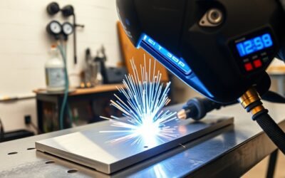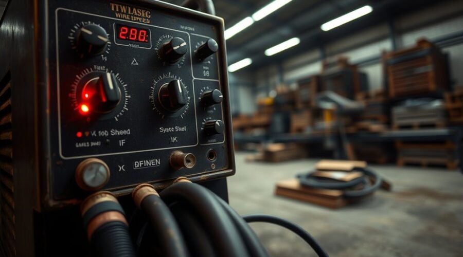
MIG welder settings depend on more than metal thickness alone. Voltage, wire feed speed, wire diameter, shielding gas, joint design, welding position, stickout, and travel speed all affect the arc. The most reliable approach is to start with the chart inside your welder or its owner’s manual, then make small adjustments while testing on scrap of the same material and thickness.
Quick Answer
There is no single MIG voltage and wire-speed setting that works for every welder. Start with your machine’s chart for the metal, thickness, wire diameter, and gas you are using. On solid-wire mild steel, wire feed speed largely determines current, while voltage is adjusted to produce a stable arc and proper bead profile.
Key Takeaways
- Use the manufacturer’s door chart or owner’s manual as the first settings reference because voltage and wire speed vary by machine, wire diameter, gas, and joint.
- On common constant-voltage MIG equipment, increasing wire feed speed generally increases welding current.
- Voltage mainly changes arc length and bead profile; it must stay balanced with wire feed speed.
- For solid-wire mild steel, ER70S-6 with an argon/CO2 blend such as C25 is a common setup, but other approved gases are also used.
- Stainless filler and gas must match the stainless grade and process; 98% argon/2% CO2 is one option, not the only one.
- Aluminum commonly uses ER4043 or ER5356 with argon-based shielding, depending on the base alloy and application.
- Always make a test weld and check fusion, bead shape, spatter, porosity, and burn-through before welding the finished part.
At a Glance
| Time Required | About 5–15 minutes to set up and run test beads |
| Difficulty | Beginner to intermediate |
| Tools Needed | MIG welder, correct wire, shielding gas if required, flowmeter/regulator, work clamp, scrap metal, pliers, wire brush, helmet, gloves, protective clothing |
| Cost | No fixed setup cost beyond the welder, wire, gas, PPE, and normal consumables |
What MIG Welder Settings Control
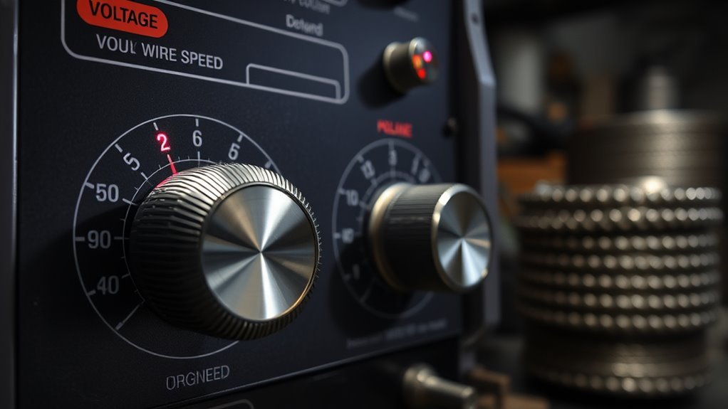
MIG welder settings, especially voltage and wire feed speed, control how the arc behaves and how much filler metal is deposited into the joint.
On a common constant-voltage GMAW machine, increasing wire feed speed generally raises welding current because more electrode is being fed into the arc. Voltage mainly changes arc length and bead profile. The two settings must remain balanced for a smooth, stable arc.
Miller’s current parameter guidance recommends starting with the owner’s manual or machine chart and accounting for material thickness, wire diameter, joint design, welding position, shielding gas, and other variables.
A MIG settings chart is a starting point, not a universal recipe. The final settings must match the wire, gas, machine, joint, and actual weld response.
Metal thickness still matters. Thin sheet needs lower current and careful travel speed to avoid burn-through, while thicker sections usually need more current, better joint preparation, or multiple passes.
Stickout also changes the weld. For common short-circuit solid-wire MIG work, a stickout around 3/8 inch is a useful starting point. Holding the gun too far away can reduce effective heat at the work and weaken gas coverage. Miller discusses these effects in its MIG welding technique guide.
Choose the Right Wire and Gas
Voltage and wire feed speed only work properly when the wire, shielding gas, polarity, and base metal are compatible.
Mild Steel
For general solid-wire mild-steel MIG welding, ER70S-6 is a common wire. A 75% argon/25% CO2 blend, often called C25, is widely used because it provides a stable short-circuit arc with moderate penetration and relatively low spatter.
C25 is not the only acceptable gas. Depending on the process and transfer mode, carbon steel GMAW can use 100% CO2 or several argon/CO2 or argon/oxygen blends. Lincoln Electric’s GMAW Shielding Gas Selection Guide lists the appropriate options by material and transfer mode.
Common solid-wire GMAW normally runs DCEP, or direct-current electrode positive. Confirm polarity on the machine because changing from solid wire to another process may require reconnecting the leads.
Stainless Steel
Stainless steel requires filler that matches the base alloy and service requirements. ER308L or ER308LSi is commonly used with many 304-series applications, while other stainless grades may require wires such as ER309L or ER316L.
Shielding gas also varies by process. A 98% argon/2% CO2 blend can work well on suitable equipment, while argon/helium/CO2 tri-mixes remain common for conventional stainless MIG. Miller recommends keeping CO2 low when welding stainless to help protect weld properties.
Aluminum
Aluminum does not universally require ER4043. ER4043 and ER5356 are both common aluminum filler wires, and the correct choice depends on the base alloy, required strength, ductility, corrosion behavior, anodizing requirements, cracking sensitivity, and service temperature.
Lincoln Electric’s aluminum filler-metal selection guide compares ER4043 and ER5356 and shows why one wire cannot be recommended for every aluminum job.
Pure argon is the most common shielding gas for many aluminum MIG applications. Argon/helium blends are also used for some applications. Do not use ordinary argon/CO2 mild-steel gas on aluminum.
Because aluminum wire is soft and difficult to push through a long conventional liner, many welders use a spool gun or push-pull system. Follow the welder and gun manufacturer’s instructions for drive rolls, liner, contact tip, and wire diameter.
Note: Aluminum does not follow a reliable rule such as “use 25% more voltage and wire speed than steel.” Use the aluminum program or parameter chart supplied for your exact machine, wire diameter, filler alloy, and thickness.
What About Flux-Cored Wire?
Flux-cored arc welding is related to MIG because both processes continuously feed wire through a gun, but FCAW uses a tubular flux-filled electrode and follows different setup rules.
Self-shielded flux-core wire does not use an external gas bottle. Many common hobby self-shielded wires use DCEN, but polarity is wire-specific, so always follow the spool label or manufacturer’s datasheet. Gas-shielded flux-cored wires may require different gas and polarity.
Because of these differences, a flux-core voltage/WFS number should not be mixed into a solid-wire MIG chart as though the two processes use identical parameters.
Use a MIG Settings Chart by Material
A MIG settings chart should identify at least the material, thickness, wire type, wire diameter, gas, and polarity. Machine-specific charts are more useful than a generic voltage number because power-source behavior varies.
For solid-wire mild steel, Miller publishes a useful rule of thumb: estimate about 1 amp for each 0.001 inch of material thickness, then select a wire size that can operate in that current range. This is only a starting estimate and should not replace an approved welding procedure.
Mild-Steel Wire Feed Speed Starting Points
When no machine chart is available, Miller gives the following general wire-feed multipliers for solid steel wire:
| Wire Diameter | General Current Range | WFS Starting Formula | Example at 125 A |
|---|---|---|---|
| .023 in. | About 30–130 A | 3.5 IPM per amp | About 438 IPM |
| .030 in. | About 40–145 A | 2 IPM per amp | About 250 IPM |
| .035 in. | About 50–180 A | 1.6 IPM per amp | About 200 IPM |
| .045 in. | About 75–250 A | 1 IPM per amp | About 125 IPM |
For example, 1/8-inch steel is 0.125 inch thick. Using the 1 amp per 0.001-inch starting rule gives roughly 125 amps. With .035-inch wire, 125 × 1.6 gives a starting wire-feed speed of about 200 IPM. With .030-inch wire, the same estimated current gives about 250 IPM.
This is why one blanket statement such as “300–400 IPM for 1/8-inch steel” can be misleading unless the wire diameter and machine are also specified.
Pro Tip: If your welder has a chart inside the wire-compartment door, use that chart before any internet chart. It was developed around that machine’s output, available wire sizes, and supported processes.
How Voltage and Wire Speed Work
Voltage and wire feed speed work together, but they do different jobs.
- Wire feed speed: Increasing WFS generally raises welding current and deposition rate on a constant-voltage MIG machine.
- Voltage: Primarily affects arc length and bead profile. Too little voltage can cause a harsh arc, stubbing, excessive convexity, and poor toe fusion. Too much can make the arc erratic and the puddle difficult to control.
- Travel speed: Moving too quickly can create a narrow bead with poor tie-in. Moving too slowly can make the weld excessively wide and overheat thin material.
- Stickout: Excessive electrode extension changes resistance heating and may reduce effective heat at the work while weakening shielding coverage.
- Joint design and position: Fillets, butt joints, gaps, vertical welding, and overhead welding can all require changes from a flat-position chart.
Voltage should therefore not be treated as a simple “more voltage equals more penetration” control. Penetration depends on the combined effect of current, voltage, travel speed, wire extension, joint preparation, gun angle, and other variables.
Balanced settings produce a stable arc, controlled puddle, sound fusion, and a bead that ties smoothly into both sides of the joint.
How to Set a MIG Welder Step by Step
- Identify the base metal. Confirm whether you are welding mild steel, stainless steel, aluminum, or another alloy.
- Measure the material thickness. Do not estimate when working near the limits of thin sheet or the machine’s output.
- Select the correct wire. Match filler classification and diameter to the base metal and expected current range.
- Check polarity. Common solid-wire GMAW normally uses DCEP. FCAW polarity depends on the wire.
- Select the shielding gas. Match the gas to the material and transfer mode rather than assuming one blend works for everything.
- Set gas flow. For light-duty indoor MIG welding, around 20 CFH is a common starting point. Increase only as needed for the nozzle, application, and manufacturer’s recommendation; excessive flow can create turbulence.
- Set wire feed speed. Start with the machine chart. If none is available for solid mild steel, use the amperage and wire-diameter formulas as a rough starting point.
- Set voltage. Use the machine chart if available. Otherwise, tune voltage until the arc is stable and the bead has good width and toe tie-in without excessive spatter.
- Set stickout and gun angle. Around 3/8 inch stickout is a useful starting point for common short-circuit solid-wire MIG. Keep the gun position consistent.
- Run a test bead. Use scrap of the same material and thickness. Check bead profile, fusion, spatter, porosity, and burn-through before welding the actual part.
Fine-Tune MIG Settings for Clean Beads
Once the starting settings are established, adjust one variable at a time. Small changes make it easier to understand what improved or worsened the weld.
With voltage and wire feed speed set, final tuning should focus on arc stability, bead profile, fusion, spatter, and repeatability.
Listen to the arc, but do not judge the weld by sound alone. A consistent arc is useful feedback, yet bead shape and fusion matter more than whether the weld matches a particular sound description.
Test welds on scrap provide the clearest feedback. A good bead should show consistent width, controlled reinforcement, and smooth tie-in at the toes without visible porosity or burn-through. For critical work, visual appearance alone does not prove weld strength; follow the required welding procedure and inspection requirements.
Common MIG Setting Problems
| Symptom | Possible Causes | What to Check |
|---|---|---|
| Wire repeatedly stubs into the work | Voltage too low, WFS too high for voltage, excessive stickout | Raise voltage slightly or rebalance WFS, then verify stickout |
| Wire burns back toward the contact tip | Voltage too high for WFS, feeding problem, incorrect contact-tip distance | Reduce voltage or correct wire feeding and gun position |
| Excessive spatter | Voltage/WFS mismatch, wrong polarity, poor gas, excessive stickout, dirty metal | Confirm chart settings, polarity, gas, stickout, and surface preparation |
| Porosity or pinholes | Inadequate shielding gas, wind, leaks, contamination, excessive stickout | Check cylinder, regulator, hose, nozzle, gas flow, drafts, and metal cleanliness |
| Burn-through | Too much current, travel too slow, gap too large, thin material overheated | Reduce settings, increase travel speed, shorten weld duration, or improve fit-up |
| High convex bead with poor toe tie-in | Insufficient heat/current, low voltage, travel too fast | Recheck WFS/current, voltage, and travel speed |
| Wide, overheated bead | Travel too slow, excessive voltage or overall heat input | Increase travel speed and return to the manufacturer’s starting range |
MIG Welding Safety Before You Adjust Settings
Warning: Welding produces intense UV radiation, hot metal, sparks, fumes, and electrical hazards. Wear an appropriate welding helmet, gloves, flame-resistant clothing, and other required PPE. Provide suitable ventilation, keep combustible materials away from the welding area, and follow the welder manufacturer’s safety instructions.
The Occupational Safety and Health Administration identifies welding fumes, UV radiation, burns, eye injuries, electrical shock, and fire among the major hazards associated with welding and cutting.
Before welding, remove or protect combustible materials, ensure the work clamp and cables are in good condition, and never weld on a container that may contain or previously contained flammable or hazardous material unless it has been made safe under an approved procedure.
Ventilation is especially important when welding stainless steel, coated or plated metals, or when working in confined or poorly ventilated spaces. Do not assume an ordinary room fan is adequate for every fume hazard.
Frequently Asked Questions
What are the optimal voltage and wire speed for MIG welding?
There is no universal voltage and wire-feed setting. Use the chart for your welder, material, wire diameter, shielding gas, thickness, joint, and position. For solid mild steel, wire feed speed is normally selected to provide the needed current, then voltage is fine-tuned until the arc is stable and the bead has proper shape and toe tie-in.
What are the correct MIG settings for .035 wire?
For solid steel .035-inch wire, Miller lists a general current range of about 50–180 amps and a starting wire-feed formula of roughly 1.6 IPM per amp. For a 125-amp starting target, that equals about 200 IPM. Voltage should come from the machine chart and then be fine-tuned for the arc and bead.
How do you set MIG wire feed speed?
Start with the welder manufacturer’s chart. For solid mild steel when no chart is available, estimate the required current from thickness, select a suitable wire diameter, and use the manufacturer’s WFS multiplier. Make a test weld and adjust only enough to achieve stable transfer, good fusion, and an appropriate bead profile.
How do you calculate wire feed speed in MIG welding?
For solid-wire mild steel, Miller gives a rough starting rule of about 1 amp for every 0.001 inch of material thickness. Then multiply the estimated amps by the wire-size factor: about 3.5 for .023 wire, 2 for .030, 1.6 for .035, or 1 for .045. Use the result only as a starting point and stay within the wire and machine’s rated operating range.
What gas flow should I use for MIG welding?
Around 20 CFH is a common light-duty indoor starting point, but the correct flow depends on the nozzle, shielding gas, joint, draft conditions, and manufacturer’s recommendation. More flow is not always better because excessive flow can create turbulence and draw air into the shielding envelope.
Should I change voltage or wire speed first?
Begin with both values from the machine chart. If you are establishing settings manually, select wire feed speed for the approximate current needed, then adjust voltage to balance the arc. During troubleshooting, change one variable at a time so you can see what actually improved the weld.
Conclusion
MIG welder settings depend on the coordinated balance of wire feed speed, voltage, wire diameter, filler type, shielding gas, polarity, stickout, travel speed, material thickness, and joint design. A manufacturer-specific chart is the best starting point because generic numbers cannot account for every machine and process combination.
For solid mild steel, approximate current and wire-feed formulas can help when no chart is available, but the final setup should always be confirmed with a test weld. Adjust one variable at a time and judge the result by arc stability, fusion, bead shape, spatter, porosity, and heat control rather than chasing one fixed voltage or IPM number.
Sources
- Miller Electric — MIG Welding: Setting the Correct Parameters — wire-size current ranges, amperage rule of thumb, wire-feed multipliers, voltage adjustment, and weld-bead troubleshooting.
- Miller Electric — MIG Welding Tips and Techniques for Beginners — stickout, shielding-gas flow, gun position, and travel technique.
- Lincoln Electric — GMAW Shielding Gas Selection Guide — gas options for carbon steel, stainless steel, aluminum, and other alloys.
- Lincoln Electric — Aluminum Filler Metal Selection — ER4043 versus ER5356 selection considerations.
- OSHA — Welding, Cutting, and Brazing: Hazards and Solutions — fumes, UV exposure, burns, electrical hazards, PPE, and workplace controls.