
Spot welding is fast enough for high-volume production, but reliable joints depend on much more than a quick burst of current. Material type, sheet thickness, electrode force, weld time, tip geometry, cooling, and surface condition all affect the finished weld. This guide explains how the process works, which settings matter, what defects look like, and how to judge weld quality.
Quick Answer
Spot welding, or resistance spot welding, joins overlapping conductive metal sheets by clamping them between copper-alloy electrodes and sending a short, high-current pulse through the joint. Electrical resistance creates heat at the sheet interface, forming a weld nugget that solidifies under pressure. Current, weld time, electrode force, surface condition, and tip geometry control the result.
Key Takeaways
Key Takeaways
- There is no universal spot-welding current or time; a qualified schedule must match the material, coating, thickness, electrode geometry, and machine.
- Low-carbon steel is relatively easy to spot weld, while galvanized steel needs closer electrode maintenance and aluminum usually requires substantially higher current.
- The electrodes do more than carry current: they apply force, contain the molten nugget, remove heat, and strongly influence nugget size.
- A good-looking surface mark does not prove the internal nugget is sound. Destructive testing or validated process monitoring is needed for meaningful quality control.
- Common failures such as expulsion, undersized nuggets, sticking, cracking, and heavy indentation usually trace back to settings, fit-up, contamination, cooling, or electrode condition.
What Is Spot Welding?
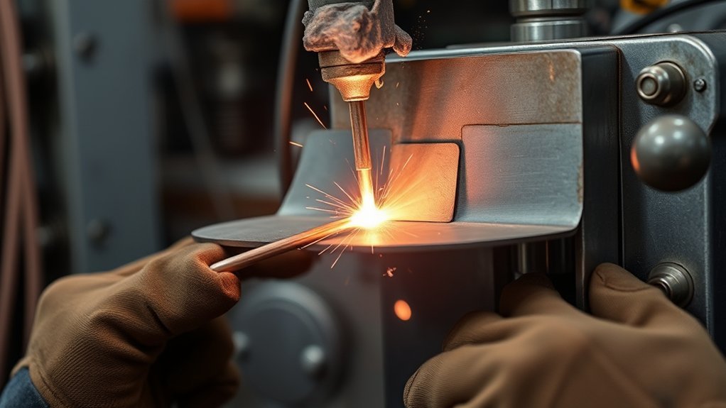
Spot welding is a resistance welding process used mainly to join overlapping sheets at individual points. Copper-alloy electrodes squeeze the sheets together and conduct current through them, creating localized resistance heating at the interface.
The metal melts only around the intended joint and forms a fused zone called the weld nugget. Current then stops while electrode force remains long enough for that nugget to solidify. No filler wire or filler rod is normally required. TWI’s spot-welding process guide describes the same combination of electrode pressure, resistance heat, and solidification under force.
A conventional multi-process welder should not be confused with a resistance spot welder. MIG, TIG, and stick equipment create an arc, while resistance spot welding sends current directly through the clamped workpieces.
Spot welding also normally needs no shielding gas. Its speed, repeatability, and ability to automate closely spaced joints make it especially useful for sheet-metal production.
How Spot Welding Works
Spot welding works by turning the electrical resistance of the workpiece stack into highly localized heat. The important controls are welding current, current duration, electrode force, and contact conditions; changing one can change the amount and location of heat produced.
Heat And Pressure
The electrodes first press the sheets together. Current then travels from one electrode, through the sheets and their mating interface, and back through the opposite electrode.
The basic heating relationship is commonly expressed as Q = I²Rt, where Q represents heat, I current, R electrical resistance, and t time. Because current is squared, relatively small current changes can have a large effect on heat generation.
There is no dependable single amperage range for every spot weld. Thin low-carbon steel may use several kiloamps, while thicker steel, high-strength material, coatings, and especially aluminum can require substantially different schedules.
| Factor | Typical Guidance | Effect |
|---|---|---|
| Welding current | Material- and thickness-dependent | Controls heat generation and nugget growth |
| Weld time | Short, precisely controlled interval | Controls total heating and fusion |
| Electrode force | Matched to the weld schedule | Controls contact resistance and contains molten metal |
Too little heat can leave an undersized or incomplete weld. Too much heat for the available electrode force can eject molten metal, a defect known as expulsion.
Weld Nugget Formation
The weld nugget begins at the faying surface, meaning the interface where the overlapping sheets touch. As current continues, the molten region grows through part of each sheet.
When the current turns off, the electrodes keep squeezing the joint during the hold period. This supports the molten region while it cools and solidifies into a metallurgical bond.
Nugget diameter is not universally 3–6 mm. It depends on sheet thickness, material, coating, electrode face, loading requirements, and the applicable weld specification. Engineering drawings or a qualified welding procedure should define the required minimum size.
Worn or mushroomed electrode tips spread the current over a larger area. This lowers current density and can gradually reduce nugget size even when the machine settings have not changed.
Spot Welding Steps
A reliable spot weld follows a controlled sequence: prepare the workpieces, establish proper fit-up and electrode force, apply the programmed current, hold the joint while it solidifies, and then inspect or test the result. Changing several settings at once makes troubleshooting much harder.
Warning: Resistance welding combines high current, powerful clamps, hot metal, and possible flying sparks. OSHA’s resistance-welding requirements address guarding, accidental activation, electrical isolation, grounding, and spark protection. Follow the machine manufacturer’s instructions and keep fingers clear of the electrode closing area.
Surface Preparation
Surface condition affects electrical contact and therefore heat generation. Remove loose rust, dirt, heavy scale, oil, paint, and other contamination that is not part of the qualified weld system.
Do not automatically grind away the zinc coating from galvanized steel. Proper resistance-welding procedures are specifically designed for coated steels; the coating usually calls for different settings and more frequent electrode dressing rather than blanket removal.
- Identify the material, coating, and sheet thickness before selecting a schedule.
- Clean unwanted contamination from the intended electrode and faying surfaces.
- Align the sheets so the overlap sits flat without an excessive gap.
- Check electrode alignment, face condition, cooling, and machine setup.
- Use the manufacturer’s or qualified welding schedule as the starting point.
If you are learning arc processes separately, remember that machines covered in guides to welders for beginners use different welding principles and settings from resistance spot equipment.
Weld Cycle Sequence
A spot-welding cycle is normally described through squeeze, weld, hold, and release or off intervals. The important point is that full electrode force should be established before welding current begins, and that force remains after current stops while the nugget solidifies.
- Squeeze: The electrodes close and build the required force on the sheet stack.
- Weld: The programmed current flows for the selected time and forms the nugget.
- Hold: Current stops, but electrode force remains while the molten region solidifies.
- Release: The electrodes open after the joint has developed enough strength to support itself.
AMADA WELD TECH’s spot-welding reference gives weld times from 0.01 to 0.63 seconds depending on metal thickness, electrode force, and electrode diameter. That broad range is more useful than treating one short timing value as correct for every machine and material.
Spot Welding Machine Parts and Electrodes
A spot-welding system needs a controlled electrical source, a mechanism that develops electrode force, electrodes that conduct current into the work, and controls that coordinate the welding cycle. Production systems may also use robotic guns, inverter controls, monitoring hardware, and automatic tip dressers.
- Power source and transformer or inverter: Deliver high welding current at the required timing.
- Weld head or welding gun: Positions the electrodes and applies controlled force.
- Copper-alloy electrodes: Carry current, apply force, contain the molten nugget, and remove heat.
- Controller: Manages current, squeeze time, weld time, hold time, and other programmed stages.
- Cooling system: Removes heat from electrodes, holders, and other current-carrying parts.
The American Welding Society’s electrode guidance notes that electrode material and nose geometry must match the work. AWS also recommends effective clean-water cooling to maximize electrode life.
Class 2 copper alloys are commonly used for steel because they balance conductivity and strength. Different alloys and face shapes may be selected for aluminum, stainless steel, coated material, tight flanges, or unequal sheet thicknesses.
Electrode cooling and maintenance are central to repeatability. Overheated or mushroomed tips change the contact area, which changes current density and shifts the weld away from the schedule that originally produced a good nugget.
Spot-welding hazards and maintenance differ from those associated with oxy-acetylene cutting equipment, so safety procedures should match the actual process in use.
Best Materials for Spot Welding
Low-carbon steel is one of the easiest materials to resistance spot weld because its electrical resistance and thermal behavior provide a comparatively forgiving process window. Stainless steel, galvanized steel, nickel alloys, titanium, and aluminum can also be spot welded with suitable equipment and procedures.
Low-carbon steel is generally the most forgiving common sheet material, but coating, strength grade, thickness, and surface condition still change the required weld schedule.
The current ISO 14373:2024 standard covers resistance spot welding of uncoated, metallic-coated, and certain weldable non-metallic-coated low-carbon steel in two- or three-sheet assemblies. Its scope includes maximum single-sheet thicknesses from 0.4 to 3.0 mm.
Galvanized steel is routinely spot welded, but zinc changes the welding window and accelerates electrode wear. Tip dressing or replacement therefore becomes more important than with bare low-carbon steel.
Higher-carbon and hardenable steels need more care because rapid heating and cooling can create hard, brittle microstructures. Procedure qualification becomes especially important as material strength and hardenability rise.
Stainless steel is spot weldable, but its electrical and thermal properties differ from mild steel. Current, force, time, and electrode material should therefore be selected for the specific grade and thickness.
Aluminum is more demanding because it conducts heat and electricity efficiently and develops a persistent oxide film. It normally requires substantially higher welding current than comparable steel and places heavy demands on electrode condition and cooling.
The current ISO 18595:2021 standard for aluminum spot welding covers aluminum sheet, extrusions, and cast material where the maximum single component thickness is within 0.6 to 6 mm. That scope does not mean every portable or benchtop spot welder can handle the entire range.
Resistance spot welding normally uses no filler electrode. That distinguishes it from arc processes that rely on consumables such as the welding rods used in stick welding.
Spot Welding Uses Across Industries
Spot welding is most valuable where manufacturers need many repeatable joints in overlapping conductive sheet or small metal components. Its short cycle and easy robotic integration make it especially attractive for high-volume production.
In the automotive industry, robotic welding guns place large numbers of resistance spot welds throughout body-in-white structures, brackets, reinforcements, and other sheet assemblies.
In battery manufacturing, smaller resistance-welding systems can join conductive tabs and straps to cells. The exact process and settings depend on cell design, tab material, thickness, and thermal limits.
Household appliances such as refrigerators and washing machines use spot welding in sheet-metal cabinets, frames, and internal assemblies.
Electronics and electrical products use smaller-scale resistance welding for thin conductive parts, terminals, enclosures, and similar components.
Building, furniture, rail, aerospace, and medical manufacturing also use resistance spot welding where material, access, design requirements, and inspection rules suit the process.
- Fast cycles support repetitive production.
- Localized heating limits overall sheet distortion.
- No filler metal or shielding gas is normally required.
- Automation can deliver highly repeatable placement and timing.
For general shop-oriented accessories rather than production spot-welding equipment, this collection of welder gift ideas covers a different category of welding gear.
Advantages and Limitations of Spot Welding
Spot welding combines speed, low consumable use, and automation well, but it is not suitable for every joint. The biggest design limitation is access: conventional resistance spot welding generally needs electrodes on opposite sides of the sheet stack.
Main advantages include:
- Very short welding cycles compared with many manual arc processes.
- No filler metal and normally no shielding gas.
- Localized heat input and relatively low overall distortion.
- Easy integration with robotic and automated equipment.
- Consistent repeatability after the process is properly qualified.
Main limitations include:
- Best suited to overlapping joints rather than unrestricted joint geometry.
- Both sides normally need to be accessible to opposing electrodes.
- Thicker or highly conductive material demands more powerful equipment.
- Electrodes wear and require cooling, dressing, and replacement.
- The internal nugget cannot be judged reliably from the surface mark alone.
Key Spot Welding Settings
The most important spot-welding settings are current, weld time, electrode force, tip geometry, and hold time. They work as a system, so increasing one parameter without considering the others can turn an acceptable weld into expulsion, deep indentation, sticking, or an undersized nugget.
| Setting | Control Target |
|---|---|
| Welding current | Enough to form the required nugget without excessive expulsion |
| Weld time | Long enough for fusion but short enough to control overheating |
| Electrode force | Stable contact and containment of the molten nugget |
| Electrode face | Correct alloy, diameter, profile, alignment, and condition for the schedule |
| Hold time | Maintain force until the nugget solidifies sufficiently |
| Cooling | Control electrode temperature and slow tip degradation |
A setting such as “5,000 amps” means little without the material, thickness, coating, electrode force, face diameter, machine type, and weld time. Production procedures use a validated combination rather than one universal amperage target.
Likewise, amperage numbers used for resistance welding should not be transferred directly from conventional arc equipment such as the machines in this guide to stick welders. The processes use current in fundamentally different ways.
Common Spot Welding Defects and Causes
Most spot-welding defects come from a mismatch between heat input, electrode force, contact condition, material, and electrode geometry. Because the nugget forms inside the joint, a weld can look acceptable from the outside and still be weak.
Undersized or incomplete nugget: Too little current, too little weld time, excessive tip-face area, poor fit-up, shunting, or unsuitable force can prevent adequate fusion.
Weld expulsion: Excessive current or weld time, insufficient electrode force, poor fit-up, or badly worn tips can allow molten metal to escape from the joint.
Electrode sticking: Excessive surface heating, contaminated tips, unsuitable electrode material, insufficient cooling, or an incorrect schedule can make the electrode adhere to the workpiece.
Deep indentation: Excessive heating, small electrode faces, misalignment, or unsuitable force can leave a deeper-than-expected electrode impression.
Cracking: Material hardenability, excessive thermal severity, or an unsuitable weld schedule can promote cracking, especially in some higher-carbon and advanced high-strength steels.
Internal voids or porosity: Contamination, expulsion, shrinkage behavior, coatings, or an unsuitable heating and hold cycle can contribute to internal discontinuities.
- Confirm the material, coating, thickness, and intended weld specification.
- Inspect electrode alignment, face diameter, wear, sticking, and cooling.
- Check fit-up and remove unwanted contamination.
- Compare the current, weld time, and force with the qualified schedule.
- Test the weld rather than judging strength by appearance alone.
Controls found on arc equipment, including machines discussed in this guide to TIG welders, should not be used as a direct reference for resistance-welding parameters.
How to Check Spot Weld Quality
A surface indentation or heat mark cannot prove that a spot weld has the required internal nugget. Quality checks should match the drawing, welding procedure, applicable standard, and the consequence of failure.
For setup and production sampling, common checks include destructive peel or chisel testing, tensile-shear testing, cross-tension testing, and metallographic cross-sections. These methods reveal whether the joint formed an adequate nugget and how it fails under load.
Production systems can also monitor signals such as dynamic resistance, electrode displacement, force, and current. The IEEE spot-welding overview describes process monitoring and adaptive control methods used to detect trends such as expulsion, inadequate fusion, surface-condition changes, and electrode wear.
Monitoring does not eliminate the need for a validated welding procedure and appropriate physical testing. Its main value is finding drift before a large batch of parts is produced outside the acceptable process window.
How to Improve Spot Weld Strength
Improving spot-weld strength starts with producing the right nugget consistently, not simply increasing current. More current can enlarge a nugget only until the process reaches expulsion, excessive indentation, electrode damage, or another quality limit.
Use clean, well-fitted parts; maintain the specified electrode face; verify cooling; and keep current, time, force, and hold time inside the qualified process window. Test welds on material that matches the real parts are far more useful than adjusting settings by appearance alone.
Electrode maintenance is especially important on galvanized steel and aluminum. As the tip face wears or mushrooms, the current density changes and the same programmed current can produce a smaller nugget.
A double-pulse welding schedule can improve performance for certain materials, but it is not a universal strength upgrade. For example, a published study of double-pulse resistance spot welding on hot-stamped steel found improved mechanical performance with an optimized two-pulse schedule. The result depended on the steel and the carefully controlled pulse parameters.
For that reason, use pulsing, tempering pulses, current stepping, or other advanced schedules only when they have been developed and verified for the actual material stack.
Cutting equipment has separate performance and durability requirements; this guide to budget plasma cutters covers that equipment category rather than spot-welding settings.
Frequently Asked Questions
Is Spot Welding Hard?
Spot welding is easy to understand, but making repeatable production-quality welds takes practice and control. You must match current, weld time, electrode force, tip condition, and material thickness, then verify the result with an appropriate test rather than relying on the surface mark alone.
Is Spot Welding Stronger Than MIG Welding?
No process is always stronger. Spot-weld strength depends on nugget size, sheet material and thickness, weld count and spacing, loading direction, and the qualified schedule; MIG strength depends on joint design, penetration, filler, and technique. Choose the process for the joint and service requirement, not a blanket strength claim.
How Thick of Metal Can You Spot Weld?
There is no single maximum thickness for every spot welder. ISO 14373:2024 covers low-carbon steel sheets with a maximum single-sheet thickness from 0.4 to 3.0 mm, while ISO 18595:2021 covers aluminum components from 0.6 to 6 mm; a specific machine may have a narrower capability.
Is a Spot Welder a TIG Welder?
No. A spot welder uses resistance heat and electrode force to form a nugget between overlapping sheets, while TIG uses an electric arc from a non-consumable tungsten electrode and usually a shielding gas. The machines, controls, joint access, and typical applications are different.
Conclusion
Spot welding is a fast and repeatable way to join overlapping sheet metal when the joint, material, and equipment suit the process. Reliable results come from treating current, weld time, force, electrode condition, cooling, fit-up, and material as one controlled system rather than relying on a single amperage or timing rule.
Start with a qualified or manufacturer-recommended schedule, make test welds on matching material, and verify the nugget with an appropriate quality test. If weld quality begins to drift, check the electrodes and contact conditions before simply increasing current.
Sources
- TWI — What Is Spot Welding?: process principles, suitable materials, galvanized steel, aluminum, and applications.
- OSHA — 1910.255 Resistance Welding: guarding, electrical, grounding, control, and spark-protection requirements.
- AMADA WELD TECH — Spot Welding: weld-cycle stages, equipment, and weld-time guidance.
- American Welding Society — Selecting Spot Welding Electrodes: electrode functions, materials, geometry, cooling, and weld-face selection.
- ISO 14373:2024: scope for resistance spot welding of uncoated and coated low-carbon steel.
- ISO 18595:2021: scope for resistance spot welding of aluminum and aluminum alloys.
- IEEE Technology Navigator — Spot Welding: process variables, weld-lobe behavior, monitoring, adaptive control, and applications.
- ISIJ International — Double-Pulse Resistance Spot Welding Study: material-specific effects of optimized double-pulse welding on hot-stamped steel.