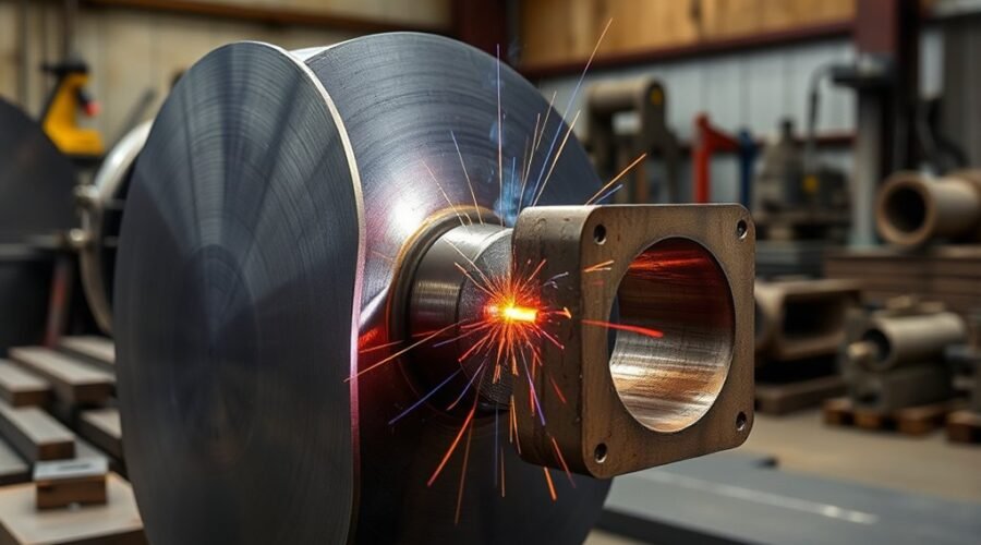
A full penetration weld, more formally called a complete joint penetration (CJP) groove weld, is a joint in which weld metal extends through the full thickness of the joint. CJP welds are used when the design requires a continuous load path through the joined section, but achieving CJP depends on the joint detail, welding procedure, fit-up, process, access, and inspection requirements—not on penetration alone.
Quick Answer
A full penetration weld, or CJP weld, is a groove weld that extends through the entire joint thickness. It may be specified with an appropriate groove-weld symbol or a CJP designation in the welding-symbol tail. A triangle is a fillet-weld symbol, not a generic symbol for complete penetration.
Key Takeaways
- A complete joint penetration weld is a groove weld in which weld metal extends through the full joint thickness.
- Do not identify CJP by a solid triangle. The triangle is associated with a fillet weld; CJP is communicated through groove-weld details and/or a CJP callout.
- CJP does not automatically make every joint stronger than the base metal. Capacity depends on the engineering design, materials, filler metal, loading, workmanship, and governing code.
- Joint preparation, root opening, backing or backgouging, welding parameters, and welder qualification must follow an approved welding procedure specification (WPS).
- Visual inspection is fundamental, while UT, RT, MT, or PT may be required depending on the applicable code, specification, joint and acceptance criteria.
What Is a Full Penetration Weld?
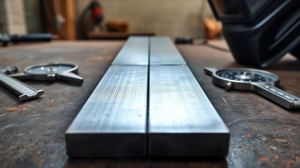
A full penetration weld, also called a Complete Joint Penetration or CJP weld, is a groove-weld condition in which weld metal extends through the entire thickness of the joint. TWI describes full penetration as a welded joint in which the weld metal fully penetrates the joint with complete root fusion.
This definition describes the required finished condition. It does not prescribe one particular groove shape, welding machine, process, current setting, or electrode.
Common CJP joint preparations include square grooves, V-grooves, bevel grooves, U-grooves and J-grooves. The preparation selected depends on material thickness, joint configuration, access from one or both sides, welding process, economics, and the applicable welding code.
For structural-steel work in the United States, AWS D1.1/D1.1M establishes requirements for structural welding, including procedure qualification, fabrication and inspection. Other industries may instead be governed by ASME, API or another project-specific standard.
A CJP joint can be designed to develop a high proportion of the connected member’s capacity and, in appropriate applications using suitable filler metal and procedures, can develop the required strength of the adjoining material. However, penetration by itself does not guarantee strength. Base-metal properties, filler-metal strength, weld soundness, heat-affected-zone behavior, joint geometry and loading all matter.
Using multi-process welders can give a fabricator more process options, but machine versatility does not replace an approved WPS or prove that a joint will achieve CJP.
What Do Full Penetration Weld Symbols Mean?
A welding symbol communicates the designer’s requirements to the fabricator. The arrow identifies the joint, the reference line carries the weld information, and the tail may contain a process, specification, procedure or other reference.
Warning: A solid triangular weld symbol is a fillet-weld symbol. It should not be described as the universal symbol for a complete joint penetration weld. CJP is a groove-weld condition and must be interpreted from the complete drawing and applicable symbol convention.
The American Welding Society’s AWS A2.4:2020 welding-symbol standard defines the system used to communicate groove welds and other welding requirements. A CJP requirement can be conveyed by an applicable groove-weld symbol without depth-of-bevel or groove-weld-size dimensions, or by including CJP in the symbol tail when that convention is used.
Common groove-weld symbols include:
- Square groove: edges remain essentially square, sometimes with a specified root opening.
- V-groove: both members are beveled to form a V.
- Bevel groove: one member is beveled while the other remains square.
- U-groove: both members have curved preparation, often used to reduce weld-metal volume in thicker sections.
- J-groove: one member has a curved J-shaped preparation.
- Flare-V and flare-bevel grooves: typically occur where curved surfaces create the groove geometry.
The symbol may also communicate the groove angle, root opening, contour, finishing method, length, location, backing, melt-through or other information. Miller’s weld-symbol guide provides practical examples of square, V, bevel and other groove symbols.
Note: The welding symbol communicates design intent, while the WPS controls how the weld is actually made. Do not invent a bevel angle, root opening, backing method or welding parameter merely because a drawing says CJP.
Understanding welding process versatility can help a beginner understand why different processes are selected for different joints, but symbol interpretation should still follow the drawing standard and project specifications.
CJP vs. PJP vs. Fillet Weld
| Feature | CJP Groove Weld | PJP Groove Weld | Fillet Weld |
|---|---|---|---|
| Joint penetration | Extends through the full joint thickness | Extends only partway through the joint thickness | Strength is based mainly on the specified fillet size and effective throat rather than full joint penetration |
| Edge preparation | Often required | Often required | Often little or no groove preparation |
| Weld volume | Can be relatively high | Usually less than an equivalent CJP preparation | Depends on leg size and weld length |
| Typical selection | Where design requires full-section load transfer or the governing code/detail requires CJP | Where a specified effective throat provides adequate capacity | T-, lap and corner joints and many general structural/fabrication connections |
| Cost and labor | Often greater because of preparation, weld volume and inspection | Can reduce weld volume where permitted | Often economical and fast to fabricate |
None of these weld types is automatically “best.” The engineer selects the weld type and required size according to the loads, member geometry, fatigue requirements, applicable code, fabrication access and economics.
Benefits of Full Penetration Welds
A properly designed and executed CJP groove weld provides a continuous welded section through the joint thickness. That can be valuable where a connection must transfer substantial tension, compression, bending or cyclic loads and the design requires full-section continuity.
High Joint Capacity
Complete joint penetration allows the entire joined thickness to participate in the welded connection. In structural design, this can allow a CJP groove weld to develop the strength required from the adjoining member when the specified filler metal, joint detail and code requirements are satisfied.
| Attribute | Practical Effect |
|---|---|
| Full joint penetration | Provides a continuous welded section through the joint thickness |
| Qualified joint detail | Supports repeatable root and sidewall fusion |
| Matching procedure and filler | Helps the connection achieve its specified mechanical properties |
| Required inspection | Confirms compliance with the governing acceptance criteria |
Strength should never be judged solely by how far a weld appears to penetrate. The complete connection—including base metal, weld metal, heat-affected zone and geometry—must satisfy the design requirements.
Does CJP Improve Corrosion Resistance?
A full penetration weld can eliminate an unfused root or inaccessible internal gap that might otherwise form a crevice in some joint designs. That can be beneficial where liquids or contaminants could collect.
However, CJP is not a corrosion-protection system. Corrosion resistance still depends on the base alloy, filler-metal compatibility, environment, weld profile, surface contamination, backing details, coatings, post-weld treatment and drainage.
Permanent backing can itself become a corrosion concern in certain services if moisture or seawater can enter beneath it. The joint therefore has to be designed for its actual environment rather than assuming that complete penetration automatically prevents corrosion.
Useful for Critical Load Paths
CJP is commonly considered where the engineering design requires full-section continuity. Examples can include structural moment connections, certain highly loaded splices, pressure-containing fabrication and some pipeline joints, although the governing code differs between industries.
- Joint geometry must permit the specified root and sidewall fusion.
- The welder and welding procedure must meet applicable qualification requirements.
- Filler metal must satisfy the WPS and applicable mechanical-property requirements.
- Preheat, interpass temperature, heat input and welding sequence must be controlled where specified.
- Inspection must follow the acceptance criteria stated by the applicable code or contract.
A CJP detail should be used because the design requires it—not simply because “more penetration” sounds safer.
When Is a CJP Weld Not Necessary?
CJP can require more edge preparation, welding time, filler metal, heat input and inspection than a smaller PJP or fillet weld. Extra weld metal can also increase shrinkage and distortion.
If engineering calculations show that a PJP groove weld or properly sized fillet weld safely carries the design load and the governing code permits it, specifying CJP can add cost without improving the required performance.
Pro Tip: Treat CJP as a design requirement, not a quality grade. A properly designed fillet or PJP weld is not an inferior weld simply because it does not penetrate the full member thickness.
How Do You Make a Full Penetration Weld?
A CJP weld is made by following a joint design and welding procedure capable of producing fusion through the entire joint thickness. There is no universal amperage, voltage, bevel angle, travel angle, polarity or root gap that works for every CJP joint.
At a Glance
| Time Required | Varies widely with material thickness, groove preparation, process, position and number of passes |
| Difficulty | Intermediate to advanced; code work may require qualified welders |
| Tools Needed | Specified welding equipment, joint-preparation tools, fit-up tools, PPE and inspection equipment required by the job |
| Cost | Project-dependent; generally increases with joint preparation, weld volume, access requirements and inspection |
Warning: Do not improvise welding parameters on a safety-critical CJP joint. Structural and pressure-containing welds should be made to the engineer’s drawing, applicable code and approved WPS by personnel with the required qualifications. Welding also creates electrical, fire, arc-radiation and fume hazards.
1. Confirm the Drawing and WPS
Identify the required weld type, joint location, base metal, filler metal, process, welding position and inspection requirements. Confirm whether the joint is a prequalified detail or requires procedure qualification under the applicable code.
2. Prepare the Joint
Clean the joint surfaces and prepare the specified square, V, bevel, U, J or other groove. Bevel angle, root face and root opening must remain within the tolerances required by the joint detail and WPS.
3. Establish Correct Fit-Up
Misalignment, an incorrect root opening or excessive gap can change penetration, weld volume and distortion. Tack welds, backing and fixtures must also comply with the approved procedure.
4. Use Backing or Backgouging When Required
Some one-sided CJP joints use backing to support the root. Other joints are welded from both sides and require removal of root-side metal by grinding, machining or another approved backgouging method before welding the second side.
Whether backing or backgouging is required depends on the joint detail and procedure. It should not be guessed in the field.
5. Weld to the Procedure
Processes such as GTAW, GMAW, FCAW, SMAW and SAW can produce complete joint penetration when used with a suitable qualified procedure. Current, voltage, wire-feed speed, travel speed, electrode manipulation, shielding gas, preheat and interpass temperature should remain within the WPS limits.
Polarity is also process-specific. For example, carbon-steel GTAW commonly uses DCEN, while solid-wire GMAW commonly uses DCEP. SMAW polarity depends on electrode classification and application. Follow the approved procedure and consumable manufacturer’s requirements rather than assuming DC+ is always best.
When selecting TIG welding equipment, remember that AC capability may be important for materials such as aluminum, but AC output itself does not make a weld CJP.
6. Control Distortion and Interpass Cleaning
Remove slag and contaminants between passes when the process requires it. Follow the specified welding sequence and temperature controls. Excessive weld volume and poor sequencing can increase shrinkage, residual stress and distortion.
7. Inspect the Finished Weld
Inspect the weld according to the governing specification. Acceptance is based on specified criteria, not simply on whether the bead looks large or appears to have deep penetration.
Backing, Back Welds and Backgouging
These terms are often confused but describe different fabrication details.
- Backing: material placed at the root to support molten weld metal during welding.
- Back weld: a weld made on the back side of a joint after the primary groove weld.
- Backing weld: weld metal placed before the main groove weld to serve as backing.
- Backgouging: removal of weld or base metal from the reverse side to reach sound metal before welding that side.
- Melt-through: visible root reinforcement produced when weld metal extends through the root of a joint.
The drawing, WPS and code determine which method is acceptable. Permanent backing should also be evaluated for fatigue, corrosion and service considerations when applicable.
How Does a Full Penetration Weld Compare to a Fillet Weld?
A CJP groove weld extends through the complete joint thickness. A fillet weld typically joins surfaces that meet at approximately a right angle or overlap and has a roughly triangular cross-section.
A fillet weld joins surfaces at an angle, creating a generally triangular weld profile; its strength is determined from its specified dimensions, effective throat, length, filler-metal properties and loading.
- CJP groove welds often require edge preparation, while fillet welds commonly require little or no groove preparation.
- CJP groove welds provide full joint penetration; fillet weld design is based primarily on weld size and effective throat.
- Fillet welds can be faster and more economical for many connections.
- CJP may be selected when the design specifically requires full-section continuity or a governing detail mandates it.
The decision therefore depends on performance requirements, fabrication economics and the applicable code rather than a rule that one weld type is always superior.
Equipment duty cycle can affect productivity on long or multi-pass welds, but it does not determine whether the finished joint qualifies as CJP.
How Are Full Penetration Welds Inspected?
Inspection requirements come from the governing code, contract documents and project quality plan. A CJP designation by itself does not mean every weld must receive radiographic or ultrasonic testing.
Visual testing (VT) is fundamental and can identify surface cracks, undercut, overlap, incorrect profile, arc strikes and other visible conditions. The American Society for Nondestructive Testing notes that volumetric methods such as ultrasonic and radiographic testing are used when internal discontinuities must be evaluated.
- VT: checks fit-up, workmanship and visible surface conditions.
- UT: can locate many internal planar or volumetric discontinuities when an appropriate procedure is used.
- RT: produces a radiographic image and can reveal many internal volumetric discontinuities.
- MT: is useful for surface and near-surface discontinuities in ferromagnetic materials.
- PT: detects surface-breaking discontinuities in suitable nonporous materials.
The applicable standard must define the examination method, coverage and acceptance criteria. An indication detected by NDE is not automatically a rejectable defect; its type, size and location have to be evaluated against the specified acceptance standard.
Common Full Penetration Weld Defects
Common CJP weld discontinuities include incomplete joint penetration, lack of fusion, cracking, porosity, slag inclusions, undercut and unacceptable weld profile. Whether a discontinuity is rejectable depends on the applicable acceptance criteria.
Lack of Fusion
Lack of fusion occurs when weld metal fails to fuse adequately with the base metal or a previous weld pass. It can significantly reduce the effective load path in a groove weld.
Common contributing factors include:
- Insufficient or poorly controlled heat input.
- Excessive travel speed.
- Poor electrode or torch placement.
- Incorrect joint preparation or fit-up.
- Slag or contamination remaining between passes.
- Parameters outside the qualified WPS range.
Good joint cleaning, proper fit-up and compliance with the WPS are more reliable controls than simply increasing current.
Incomplete Joint Penetration
Incomplete joint penetration occurs when the weld does not extend through the required joint thickness. In a weld specified as CJP, this means the finished joint has not achieved the required penetration condition.
Possible causes include an unsuitable root opening or root face, incorrect joint preparation, insufficient root access, poor technique, incorrect parameters or failure to perform required backgouging.
Cracking and Porosity
Cracking is among the most serious weld discontinuities. It can result from hydrogen, high restraint, unsuitable filler metal, susceptible base metal, poor temperature control, unfavorable weld-bead shape or solidification behavior.
Weld-bead geometry can influence solidification cracking. TWI notes that excessively deep, narrow weld beads can promote centerline cracking, while excessively wide and shallow shapes can create other solidification problems. There is no universal rule that a width-to-depth ratio above 1.2 makes a CJP weld unstable.
Porosity forms when gas becomes trapped as the weld solidifies. Contamination, moisture, inadequate shielding, excessive gas turbulence, surface coatings or incorrect process conditions can contribute.
The correct shielding gas composition is important for gas-shielded processes, but gas selection must match the wire, material, transfer mode and approved procedure.
Slag Inclusions, Undercut and Distortion
Slag inclusions can occur when slag from a flux-producing process becomes trapped between passes or along groove faces. Thorough interpass cleaning and correct bead placement help reduce the risk.
Undercut is a groove melted into the base metal near the weld toe that is not adequately filled with weld metal. Excessive current, travel speed, arc length or poor manipulation can contribute, depending on the process.
Distortion is not necessarily a weld defect, but CJP joints can involve substantial weld volume and heat input. Balanced joint designs, welding sequence, fixtures and controlled heat input can help manage shrinkage.
Safety When Making CJP Welds
CJP welding involves the same major hazards as other arc-welding operations: electric shock, ultraviolet and infrared radiation, burns, hot metal, fire, fumes and gases.
The U.S. Occupational Safety and Health Administration’s welding, cutting and brazing requirements address eye and face protection, protective clothing, ventilation and other controls. Local exhaust or other ventilation may be required to prevent hazardous concentrations of fumes, particularly in enclosed or confined spaces.
- Wear an appropriate welding helmet, eye protection, gloves and protective clothing.
- Control sparks, slag and combustible materials under the applicable hot-work procedure.
- Provide adequate ventilation and use additional respiratory protection when required by the hazard assessment.
- Inspect welding equipment and leads before use.
- Use extra precautions around confined spaces and pressure-containing equipment.
- Never weld a closed container unless it has been properly prepared under an approved procedure.
Frequently Asked Questions
What Is the Difference Between Full and Partial Penetration Welds?
A complete joint penetration (CJP) groove weld extends through the full thickness of the joint. A partial joint penetration (PJP) groove weld extends only partway through the joint and has a specified effective weld size. Either can be appropriate when selected and designed for the required load and applicable code.
What Is the Difference Between a Fillet Weld and a Full Penetration Weld?
A fillet weld typically joins intersecting or overlapping surfaces and has a roughly triangular cross-section. A CJP groove weld extends through the complete joint thickness. Their strengths are determined differently, and either may be appropriate depending on the engineered connection.
Does a Weld Have to Have 100% Penetration to Be Strong?
No. Many properly designed fillet and PJP welds safely carry their required loads without complete joint penetration. Strength depends on weld size, effective throat, length, filler metal, base material, loading, joint design and workmanship. CJP is required only when the design or applicable specification calls for it.
What Is a Penetration Weld?
Joint penetration describes how far the weld extends into the joint from the weld face, excluding reinforcement. A groove weld may be specified for complete joint penetration or partial joint penetration depending on the required effective weld size and design.
Is a Triangle the Symbol for a Full Penetration Weld?
No. The basic triangular symbol represents a fillet weld. CJP is a groove-weld condition and is communicated through the applicable groove-weld symbol and dimensions or by a CJP notation in the welding-symbol tail, depending on the drawing and applicable AWS A2.4 convention.
Does Every CJP Weld Need Ultrasonic or Radiographic Testing?
No. The required inspection method and extent are specified by the governing code, contract documents and quality plan. Visual inspection is fundamental, while ultrasonic, radiographic, magnetic-particle or penetrant testing may be added where required.
Conclusion
A full penetration weld or CJP groove weld extends through the complete joint thickness and can provide the full-section continuity required by demanding welded connections. The critical point is that CJP is a required weld condition—not simply a deep-looking bead or a triangular welding symbol.
Reliable CJP fabrication starts with the correct drawing, joint detail and WPS, followed by accurate fit-up, qualified welding, appropriate backing or backgouging where required, controlled parameters and inspection to the governing acceptance criteria. When CJP is not required, a properly engineered PJP or fillet weld may provide the necessary performance with less preparation, weld metal and distortion.
Sources
- American Welding Society — AWS D1.1/D1.1M Structural Welding Code—Steel — current structural-steel welding, procedure, fabrication and inspection requirements.
- American Welding Society — AWS A2.4:2020 — welding, brazing and nondestructive-examination symbol conventions.
- TWI — What Is Welding? — definitions of full and partial penetration welds.
- Miller — How to Read and Understand Weld Symbols — practical groove-weld, backing and melt-through symbol guidance.
- ASNT — Visual Testing Overview — capabilities and limitations of visual and volumetric nondestructive testing.
- OSHA 29 CFR 1910.252 — welding, cutting and brazing safety, PPE and ventilation requirements.