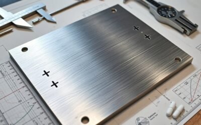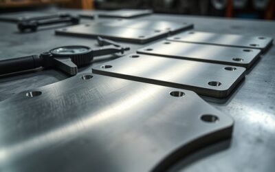
Weld quality testing determines whether a welded joint meets the requirements set by its drawing, specification, contract, or governing code. A complete inspection program may combine visual testing, surface and volumetric non-destructive testing (NDT), and destructive mechanical tests. The correct method depends on the material, weld geometry, expected discontinuities, service risk, and the acceptance criteria that apply to the job.
Quick Answer
Weld quality is checked with visual testing and, when required, methods such as liquid penetrant, magnetic particle, ultrasonic, or radiographic testing. Destructive tests such as bend and tensile tests may verify mechanical performance. A weld passes only when its measured indications and test results satisfy the acceptance criteria specified for that particular job.
Key Takeaways
- Visual testing is normally the first inspection step, but it cannot determine internal weld soundness.
- Liquid penetrant and magnetic particle testing target surface or near-surface discontinuities, while ultrasonic and radiographic testing can evaluate internal regions.
- A discontinuity is not automatically a rejectable defect; the applicable code, specification, or engineering acceptance criteria determine whether it is acceptable.
- AWS D1.1, ASME BPVC Section IX, API 1104, ISO 9606, ISO 5817, and ISO 17635 serve different purposes and should not be treated as interchangeable standards.
- No single test method finds every possible flaw, so critical work may require more than one inspection method.
Why Weld Quality Testing Matters
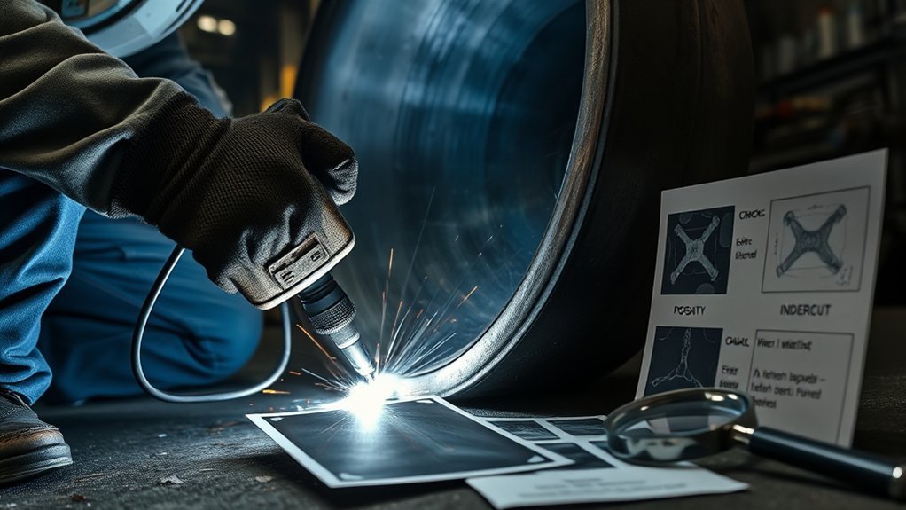
Weld quality testing helps protect structural integrity by finding unacceptable workmanship, dimensional problems, and material discontinuities before a component enters service. The required level of inspection should reflect the consequences of failure rather than relying on the same test for every weld.
Inspection can begin before the arc is struck. Pre-weld checks may verify joint preparation, material identification, cleanliness, fit-up, welding procedure requirements, consumables, and welder qualifications. During welding, inspectors may monitor parameters such as preheat, interpass temperature, bead placement, cleaning between passes, shielding, and compliance with the approved procedure.
Post-weld examination evaluates the completed joint against the specified requirements. Depending on the application, this may involve visual testing alone or a combination of visual, penetrant, magnetic particle, ultrasonic, radiographic, leak, or destructive testing.
Codes and standards provide the framework, but their roles differ. AWS D1.1/D1.1M:2025-AMD1 covers structural-steel welding requirements including fabrication, qualification, inspection, and acceptance. ASME BPVC Section IX, by contrast, is primarily a qualification standard for welding, brazing, and fusing procedures and personnel rather than a universal finished-weld acceptance code.
Equipment also affects process capability, but buying a better machine does not guarantee a weld will meet inspection requirements. If you are comparing TIG equipment for fabrication work, this guide to the Everlast PowerTIG and other TIG welders provides additional equipment context.
Common Weld Defects and Flaws
Weld inspection starts with an important distinction: a discontinuity is an interruption or irregularity in the normal structure of a material or weld, while a defect is a discontinuity that does not meet the applicable acceptance criteria. That means an indication found during inspection is not automatically cause for rejection.
Note: Whether an imperfection is acceptable depends on its type, dimensions, location, orientation, distribution, service conditions, and the governing specification. Avoid applying one generic defect limit to every welded structure.
Common weld discontinuities include lack of fusion, incomplete penetration, porosity, slag inclusions, cracks, undercut, overlap, excessive reinforcement, burn-through, and dimensional mismatch.
- Lack of fusion: weld metal fails to fuse adequately with the base metal or a previous weld bead. Planar lack of fusion can be particularly significant because its orientation may create a strong stress concentration.
- Incomplete penetration: the weld does not extend through the intended joint root or specified depth.
- Porosity: gas cavities remain in the solidified weld metal. Acceptance depends on size, quantity, spacing, and the governing criteria.
- Slag inclusion: nonmetallic material becomes trapped in the weld, often between passes or at fusion boundaries.
- Cracks: fracture-like discontinuities can occur in weld metal, the heat-affected zone, or base material and generally require careful evaluation.
- Undercut: a groove melted into the base metal beside the weld toe or root remains insufficiently filled.
A discontinuity becomes a rejectable defect when it exceeds the acceptance criteria that govern the specific weld.
Prevention depends on correct joint preparation, process settings, consumable selection, cleaning, shielding, heat control, and welder technique. Electrode selection also matters for applicable processes; this guide to all-around welding rods explains common electrode choices for general fabrication.
Which Weld Codes and Standards Apply?
The correct welding standard depends on the product, material, jurisdiction, contract, service conditions, and work scope. One of the most common mistakes in weld-quality discussions is treating fabrication codes, qualification standards, NDT method standards, and acceptance standards as if they perform the same job.
| Standard | Primary Role | Typical Application |
|---|---|---|
| AWS D1.1/D1.1M:2025-AMD1 | Structural welding requirements, qualification, fabrication, inspection, and acceptance | Common carbon and low-alloy structural steels |
| ASME BPVC Section IX:2025 | Procedure and personnel qualification | Work performed under ASME construction codes and other specifications that invoke Section IX |
| API 1104, 22nd Edition | Pipeline welding, qualification, examination, and related requirements | Pipelines and related facilities within its scope |
| ISO 9606-1:2012 | Qualification testing of welders | Manual and partly mechanized fusion welding of steels within its scope |
| ISO 5817:2023 | Quality levels for weld imperfections | Fusion-welded steel, nickel, titanium, and their alloys within its scope |
| ISO 17635:2025 | General rules for selecting and applying NDT to welds | Metallic weld inspection and NDT method selection |
The edition required by a contract or regulator may differ from the newest published edition. Inspectors should therefore verify the project documents before applying acceptance limits.
Understanding the welding process is also important because procedure qualification, essential variables, joint preparation, and inspection access vary by process. For a beginner-focused overview of machine and process choices, see this guide to MIG, TIG, and stick welding processes.
Code Families
The applicable code family is determined by the product and service rather than personal preference. Structural steel, pressure equipment, pipelines, reinforcing steel, naval fabrication, and general ISO-based manufacturing can each invoke different sets of requirements.
- AWS D1.1/D1.1M: structural steel.
- ASME BPVC Section IX: welding, brazing, and fusing procedure/personnel qualification when invoked by the applicable construction rules.
- API 1104: welding of pipelines and related facilities.
- ISO 9606: welder qualification.
- ISO 3834: quality requirements for fusion welding of metallic materials.
- ISO 14731: welding coordination tasks and responsibilities.
- ISO 17660: welding of reinforcing steel within its defined scope.
- NAVSEA and applicable military specifications: specialized defense and naval work when contractually invoked.
ASTM E190-21 is an active test method for guided-bend testing used to evaluate weld soundness and ductility under its stated scope.
Application-Specific Standards
Application-specific standards should be selected before inspection begins because the governing document determines required qualifications, examination extent, techniques, reporting, and acceptance limits.
API Standard 1104, for example, applies to welding of pipelines and related facilities within its scope. It should not be reduced to a statement that all pipeline welds require one specific NDT method. Examination requirements depend on the applicable provisions and project requirements.
Likewise, ISO 9606-1:2012 qualifies welders for fusion welding of steels; it does not replace a product-specific fabrication code or a separate weld-imperfection acceptance standard.
Acceptance Criteria
Acceptance criteria answer the practical question: Is the observed indication or measured discontinuity acceptable for this weld? The answer must come from the governing construction code, product standard, drawing, specification, or contract.
Within the ISO system, ISO 5817:2023 specifies quality levels for imperfections in specified fusion-welded joints. ISO 17635:2025 provides general guidance for selecting NDT methods and relating examination approaches to applicable quality requirements.
- Visual testing checks accessible surfaces and dimensions.
- PT and MT can reveal surface-breaking discontinuities under suitable material and surface conditions.
- UT and RT can evaluate internal regions, but their capabilities differ by flaw orientation, material, thickness, geometry, and technique.
- Mechanical tests evaluate properties such as ductility or strength on test specimens.
- Final acceptance must use the specified acceptance criteria rather than an inspector’s personal judgment alone.
Visual Inspection Basics
Visual testing is one of the most important and economical weld-inspection methods. It can be performed before, during, and after welding and often identifies conditions that should be corrected before more expensive examination is attempted.
ISO 17637:2016 specifically addresses visual testing of fusion welds in metallic materials and can also be applied to the joint before welding.
Before, During, and After Welding
Before welding, inspection may cover:
- material identification and condition;
- joint geometry and root opening;
- alignment and fit-up;
- surface cleanliness;
- consumable and procedure requirements;
- welder qualification where required.
During welding, checks may include:
- preheat and interpass temperature;
- weld sequence and bead placement;
- cleaning between passes;
- shielding-gas protection where applicable;
- visible cracking, arc strikes, or other process problems.
After welding, visual inspection may evaluate:
- cracks and other visible surface discontinuities;
- undercut, overlap, porosity, and surface profile;
- weld size and length;
- reinforcement and toe transition;
- misalignment and dimensional conformity;
- surface condition and completeness.
Pro Tip: Complete the required visual examination and surface preparation before advanced NDT. Poor access, heavy scale, spatter, coating, roughness, or incorrect geometry can interfere with later testing and create unnecessary rework.
Visual testing can use adequate lighting, mirrors, magnification, straightedges, rulers, fillet-weld gauges, bridge-cam gauges, or other dimensional tools as appropriate. It cannot prove that a weld is internally sound.
Clear vision during fabrication helps prevent workmanship problems, but a welding helmet is not a substitute for dedicated inspection lighting and measuring equipment. If you are comparing helmet optics for welding work, this guide to Lincoln welding helmet optics provides additional equipment information.
Non-Destructive Weld Testing Methods
Non-destructive testing evaluates a component without intentionally destroying its future usefulness. Common weld methods include visual testing (VT), liquid penetrant testing (PT), magnetic particle testing (MT), ultrasonic testing (UT), and radiographic testing (RT).
The correct method depends on the expected flaw type, material properties, thickness, geometry, surface condition, access, inspection extent, and applicable acceptance standard. ISO 17635:2025 specifically uses factors such as material, thickness, welding process, quality requirements, and extent of examination when guiding NDT selection.
| Method | Best Suited For | Important Limitation |
|---|---|---|
| VT | Visible surface and dimensional conditions | Cannot see hidden internal discontinuities |
| PT | Surface-breaking discontinuities in suitable nonporous materials | Does not find closed subsurface flaws; surface condition is critical |
| MT | Surface and some near-surface discontinuities | Limited to ferromagnetic materials |
| UT | Internal discontinuities, especially suitably oriented planar flaws | Technique and detectability depend strongly on geometry, material, orientation, and operator competence |
| RT | Internal density/volumetric differences with a permanent image record | Radiation controls are required; some planar flaws can be difficult to detect depending on orientation |
The trade-offs and running costs of these methods vary considerably. High-risk or code-governed work may require a specified combination rather than whichever method is cheapest or most convenient.
Visual Weld Inspection
Visual inspection is usually the first NDT method applied because it can rapidly detect visible problems without complex equipment. Inspector competence, adequate lighting, access, surface cleanliness, and a defined procedure are still essential.
Common visible conditions include:
- surface cracks;
- undercut;
- overlap;
- surface porosity;
- incorrect weld size;
- excessive or insufficient reinforcement;
- misalignment;
- arc strikes or unacceptable surface damage.
Passing a visual examination does not prove that the weld is free of internal discontinuities. When subsurface examination is required, another qualified method must be selected.
Liquid Penetrant Testing
Liquid penetrant testing detects discontinuities that are open to the surface of a suitable nonporous material. In a typical process, the surface is cleaned, penetrant is applied and allowed to dwell, excess penetrant is removed, and developer helps draw penetrant back out of surface openings so indications can be evaluated.
PT can be useful on many nonferromagnetic as well as ferromagnetic materials, but it only detects discontinuities connected to the surface. Dirt, paint, scale, smeared metal, excessive roughness, or porous material can reduce reliability or create misleading indications.
Magnetic Particle Testing
Magnetic particle testing magnetizes a ferromagnetic component. Leakage fields caused by appropriately oriented surface or near-surface discontinuities attract magnetic particles and produce visible indications.
MT is often effective for finding fine cracking in carbon and low-alloy steels, but it is not applicable to nonferromagnetic materials such as most austenitic stainless steels, aluminum, or copper alloys. Magnetization direction also matters because detectability is best when the discontinuity interrupts the magnetic field effectively.
Radiographic and Ultrasonic Testing
Radiographic and ultrasonic testing extend inspection into regions that cannot be evaluated by direct visual examination, but they work on very different physical principles.
Radiographic testing uses penetrating ionizing radiation, including X-rays or gamma rays in applicable industrial techniques, to produce an image based on differences in radiation attenuation through the component. Traditional systems use film, while modern techniques may use digital detectors. RT is often effective for volumetric discontinuities such as certain porosity and inclusions, but flaw orientation and component geometry strongly influence detectability.
Warning: Industrial radiography uses ionizing radiation. It must be performed only under applicable radiation-control procedures by properly trained and authorized personnel. Required exclusion zones, shielding, monitoring, licensing, and regulatory controls must be followed. Do not attempt industrial RT as an unqualified DIY inspection method.
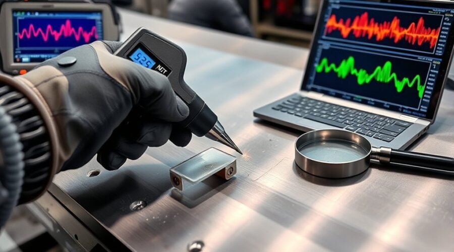
Ultrasonic testing introduces high-frequency sound into the material and evaluates reflected or diffracted signals from interfaces and discontinuities. UT can provide information about location and response without ionizing radiation and is well suited to many weld inspections, particularly where geometry and materials support a qualified technique.
ISO 17640:2018 specifies techniques, testing levels, and assessment for manual ultrasonic examination of defined fusion-welded joints. Its scope illustrates an important point: UT capability must not be generalized without considering material, thickness, joint geometry, temperature, and technique.
Neither UT nor RT should be described as universally superior. A planar lack-of-fusion indication may favor one inspection approach, while scattered volumetric porosity may favor another. Access, material, thickness, record requirements, cost, safety controls, and the governing code all influence method selection.
Destructive Weld Testing Methods
Destructive weld testing uses specimens that are cut, bent, pulled, fractured, etched, or otherwise permanently altered to evaluate weld performance or reveal internal conditions. These tests are common in procedure qualification, welder qualification, production testing, research, and failure investigation when required by the applicable standard.
| Test | What It Evaluates |
|---|---|
| Guided bend | Ductility and weld soundness as the specimen is bent |
| Tension test | Tensile strength and fracture location |
| Nick-break or fracture test | Exposes a fracture surface so internal imperfections may be examined |
| Macroetch examination | Cross-sectional weld profile, fusion, penetration, and related features |
| Fillet-weld break test | Fusion and internal condition of applicable fillet-weld test specimens |
ASTM E190-21 covers guided-bend testing for determining weld soundness and ductility in ferrous and nonferrous products within its scope.
Destructive testing does not normally mean destroying every production weld. It is frequently performed on qualification coupons, procedure test plates, sample specimens, or designated production test pieces.
Using a multi-process welder can provide fabrication flexibility, but machine versatility does not replace procedure qualification, controlled test specimens, or code-required inspection.
How to Choose a Weld Testing Method
Start with the governing specification rather than the inspection equipment available in the shop. If the code already specifies the examination method, extent, technique, and acceptance level, those requirements control.
- Identify the governing code or specification. Confirm the required edition and any project-specific additions.
- Identify the likely discontinuities. Surface cracking, lack of fusion, porosity, and dimensional problems do not have identical detection requirements.
- Check the material. MT, for example, requires a ferromagnetic material.
- Consider weld geometry and thickness. Access and sound/radiation paths affect UT and RT feasibility.
- Choose the required examination extent. Sampling and 100% examination have very different meanings.
- Use qualified personnel and procedures where required. Sophisticated equipment cannot compensate for an invalid technique or unqualified interpretation.
- Apply the correct acceptance criteria. Detection and acceptance are separate steps.
Weld Testing Tools and Checklists
A disciplined inspection plan uses stage-specific checks rather than waiting until the weld is complete.
| Stage | Typical Tools or Records | Main Focus |
|---|---|---|
| Pre-weld | Drawings, WPS, gauges, thermometer, material records | Materials, preparation, fit-up, cleanliness, qualifications, preheat requirements |
| During welding | Temperature tools, procedure records, visual checks | Parameters, interpass cleaning, heat control, sequence, workmanship |
| Post-weld | Lighting, weld gauges, VT/PT/MT/UT/RT equipment as required | Dimensions, surface condition, discontinuities, required NDT, acceptance |
| After repair | Repair procedure, inspection report, applicable NDT equipment | Removal of the original unacceptable condition and verification of the repaired area |
Useful visual-inspection equipment can include flashlights, mirrors, magnification, weld gauges, rulers, straightedges, temperature-measuring devices, and documentation tools. PT, MT, UT, and RT require their own appropriate equipment, procedures, calibration or verification steps, and trained personnel.
Inspection records should identify the component or weld, method used, examination extent, procedure or technique, relevant settings where required, indications found, acceptance criteria, disposition, repair status, and reinspection results.
Good optical clarity can improve the welder’s ability to see the puddle during fabrication, although inspection itself still requires suitable lighting and inspection tools. For equipment comparisons, see this guide to welding helmets with good optical clarity.
Repair and Reinspection
When an indication exceeds the applicable acceptance criteria, the next step is controlled disposition rather than an improvised repair. Depending on the governing requirements, the weld may be accepted as-is through an authorized engineering disposition, repaired, removed and rewelded, or rejected.
A repair workflow commonly includes:
- marking and documenting the unacceptable area;
- determining the permitted repair method;
- removing the unacceptable discontinuity when required;
- confirming adequate removal before rewelding where specified;
- performing the repair under the applicable procedure;
- repeating the required examination on the repaired area;
- recording the final disposition.
Reinspection matters because a repair can introduce new discontinuities even when the original flaw has been removed.
Limits of Weld Quality Testing
No inspection method provides a guarantee that a weld contains zero imperfections. Detection probability depends on the method, technique, equipment, surface condition, geometry, material, flaw orientation and size, access, calibration or reference standards, and inspector competence.
For this reason, weld quality assurance should combine prevention and verification. Qualified procedures, suitable materials, trained welders, controlled parameters, inspection, testing, documentation, and engineering design all contribute to reliable welded construction.
Frequently Asked Questions
What are the different methods used to test weld quality?
Common methods include visual testing, liquid penetrant testing, magnetic particle testing, ultrasonic testing, radiographic testing, and destructive mechanical or metallographic tests. The correct combination depends on the weld, material, expected discontinuities, governing code, and required acceptance criteria.
What methods are used for welding defect testing?
Visual testing finds visible surface and dimensional problems. PT detects surface-breaking discontinuities in suitable nonporous materials. MT detects surface and some near-surface discontinuities in ferromagnetic materials. UT and RT evaluate internal regions. Specialized methods such as eddy-current or acoustic-emission testing may be used for particular applications, but they are not interchangeable with the standard weld-examination methods.
What are seven common welding defects or discontinuities?
Seven commonly discussed weld discontinuities are cracks, lack of fusion, incomplete penetration, porosity, slag inclusions, undercut, and overlap or excessive spatter-related surface conditions. Whether a discontinuity is a rejectable defect depends on the applicable acceptance criteria.
What ISO standards are used for welding quality?
Important examples include ISO 3834 for fusion-welding quality requirements, ISO 9606 for welder qualification, ISO 14731 for welding coordination responsibilities, ISO 5817 for quality levels of weld imperfections, ISO 17635 for general NDT selection rules, ISO 17637 for visual testing, and method-specific standards for UT, RT, PT, and MT. The required standards depend on the product and contract.
Can visual inspection prove that a weld is internally sound?
No. Visual testing can identify accessible surface and dimensional conditions, but it cannot establish the absence of hidden internal discontinuities. If internal examination is required, an appropriate method such as UT or RT must be selected according to the governing requirements.
Does every weld require ultrasonic or radiographic testing?
No. The required examination method and extent come from the applicable code, specification, drawing, contract, engineering requirement, or inspection plan. Some welds may require visual testing only, while critical work may require additional surface or volumetric NDT.
Conclusion
Weld quality testing is not one test or one acceptance number. It is a controlled process that begins with the correct procedure and continues through pre-weld checks, in-process control, visual examination, any required NDT or destructive testing, acceptance review, documentation, and reinspection after repair.
Visual, penetrant, magnetic particle, ultrasonic, and radiographic methods each reveal different types of information. Destructive tests can provide direct evidence of mechanical behavior or expose a weld cross-section or fracture surface. The strongest inspection plan matches these tools to the material, weld geometry, expected discontinuities, service risk, and governing requirements.
Most importantly, detection and acceptance are separate decisions. An indication becomes a rejectable defect only when it fails the criteria that apply to that specific weld.
Sources
- American Welding Society — AWS D1.1/D1.1M:2025-AMD1 — structural-steel welding, qualification, inspection, and acceptance scope.
- ASME — BPVC Section IX:2025 — welding, brazing, and fusing procedure and personnel qualification.
- American Petroleum Institute — API Standard 1104, 22nd Edition — welding of pipelines and related facilities.
- ISO 5817:2023 — quality levels for imperfections in applicable fusion-welded joints.
- ISO 17635:2025 — general rules for selecting NDT methods and evaluating weld examination results.
- U.S. Occupational Safety and Health Administration — Ionizing Radiation Hazards — industrial radiography applications and radiation hazards.