Plug and slot weld symbols look simple, but a small dimension can completely change the fabrication requirement. Under current AWS notation, you must read the basic symbol together with its size, depth of filling, spacing, quantity, side placement, countersink, contour, and drawing details. The most important first step is identifying which welding-symbol standard the drawing uses.
Quick Answer
Under AWS A2.4:2020, plug and slot welds use the same basic rectangular weld symbol. A plug weld is identified by an Ø-prefixed size to the left; a slot weld uses width to the left and length to the right. Symbol placement also identifies which member contains the hole or slot.
Key Takeaways
- AWS A2.4:2020 no longer includes the diameter mark as part of the basic plug weld symbol, but Ø is still placed before the plug-size dimension.
- For a plug weld, the size to the left is the hole diameter at the faying surface; for a slot weld, the value to the left is slot width and the value to the right is slot length.
- A depth value inside the symbol specifies partial filling. If that depth dimension is omitted, complete filling is required.
- Under AWS convention, a symbol below the reference line identifies the arrow-side member; a symbol above it identifies the other-side member.
- Pitch is center-to-center spacing. Slot location and orientation, and non-straight plug layouts, may need additional dimensions on the drawing.
- Do not use a plug or slot weld symbol to specify a fillet weld made in a hole or slot; AWS treats that as a fillet-weld application.
What Are Plug and Slot Weld Symbols?
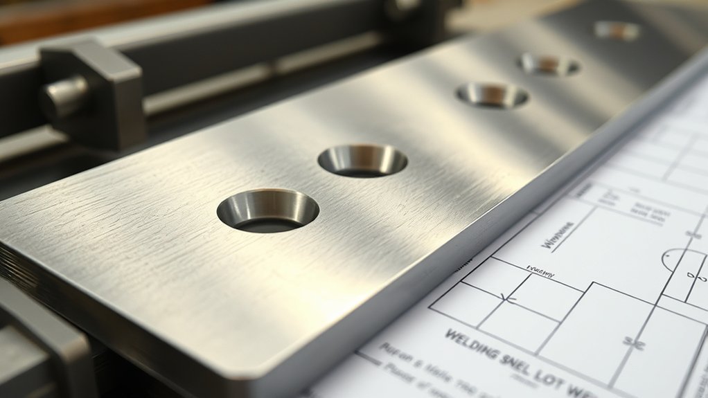
Plug and slot weld symbols identify welds made through holes or slots in one overlapping member so the weld metal joins that member to the member beneath it. A plug weld uses a generally round hole, while a slot weld uses an elongated opening.
The governing reference for U.S.-style notation is AWS A2.4:2020, Standard Symbols for Welding, Brazing, and Nondestructive Examination. The standard defines how welding requirements are communicated; it does not by itself determine whether a joint is structurally adequate or establish the welding procedure.
One important 2020 change is easy to miss: the diameter symbol Ø is no longer part of the basic plug weld symbol. It is still required when the plug-size dimension is written to the left of that symbol. Therefore, the safest way to distinguish a plug callout from a slot callout is to read the dimensions around the rectangular symbol instead of relying on the rectangle alone.
For plug welds, the left-side size is the hole diameter at the faying surface, meaning the contacting surface between the overlapping members. For slot welds, width is measured along the minor axis at the faying surface, while length is measured along the major axis.
Depth of filling, quantity, pitch, countersink angle, contour, finishing method, and drawing dimensions may add further requirements. If no depth-of-filling value appears inside the symbol, AWS notation specifies complete filling rather than partial filling.
Equipment choice is separate from symbol interpretation, but fabricators working across different processes may also find this overview of multi-process welders useful when planning general shop capability.
Weld Symbol vs. Welding Symbol
The terms weld symbol and welding symbol are related but not identical. The weld symbol is the small graphical mark that identifies the type of weld. The complete welding symbol includes the reference line, arrow, weld symbol, dimensions, supplementary symbols, and, when needed, a tail containing specifications or other information.
Note: Read the entire welding symbol. A rectangular plug/slot mark by itself cannot tell you the complete size, side, spacing, fill depth, location, orientation, or finish requirement.
Plug Weld vs. Slot Weld Symbols at a Glance
| Feature | Plug Weld | Slot Weld |
|---|---|---|
| Opening | Round hole | Elongated slot |
| Dimension to left | Ø + plug size | Slot width |
| Dimension to right | Pitch when repeated in a straight line | Slot length; pitch follows after a hyphen when required |
| Depth value | Inside symbol for partial filling | Inside symbol for partial filling |
| Quantity | Number in parentheses | Number in parentheses |
| Orientation | Hole locations may require drawing dimensions | Location and orientation are specified on the drawing |
How to Read a Plug Weld Symbol
A plug weld symbol identifies a weld deposited through a hole in one member to join it to the overlapping member beneath it. Under AWS A2.4:2020, the rectangle is the basic weld symbol, while the plug size is written to its left and preceded by Ø.
Read a plug weld callout in this order:
- Check which side of the reference line contains the symbol. Below the line means the hole is in the arrow-side member; above the line means it is in the other-side member.
- Read the plug size to the left. The Ø-prefixed value specifies the hole diameter at the faying surface.
- Look inside the symbol for depth of filling. A stated value means partial filling. If the depth dimension is omitted, complete filling is required.
- Read pitch to the right when plugs repeat in a straight line. Pitch is the center-to-center distance.
- Check the number in parentheses. When a definite quantity is required, AWS places the number on the same side of the reference line as the weld symbol.
- Check for countersink, contour, finish, and drawing dimensions. These may change the hole preparation or final weld profile.
If plug welds are arranged in something other than a straight line, the layout should be dimensioned on the drawing rather than inferred from a single pitch value.
Pro Tip: Do not stop after seeing Ø and a number. Read the symbol from side placement through size, depth, quantity, spacing, contour, and drawing notes before deciding what the callout requires.
For general machine-selection background rather than symbol interpretation, see this guide to welders for home use.
How to Read a Slot Weld Symbol
A slot weld is made through an elongated opening rather than a round hole. Under AWS notation, the slot width appears to the left of the rectangular weld symbol. Width is the minor-axis dimension of the slot at the faying surface.
The slot length appears to the right. Length is the major-axis dimension at the faying surface. When repeated slots require a pitch, the center-to-center spacing follows the length after a hyphen.
For example, the information to the right follows the logic length-pitch when both dimensions are specified. Do not confuse the pitch with the clear gap between slots; pitch is measured center to center.
Depth of filling works the same way as it does for plug welds. A partial depth is written inside the symbol. If the depth dimension is absent, complete filling is required.
When multiple slots are required, the quantity is shown in parentheses on the same side of the reference line as the weld symbol. AWS also requires the location and orientation of slot welds to be shown on the drawing, because the rectangular weld symbol alone does not communicate the direction in which the physical slot runs.
Readers still learning the practical differences among welding processes can use this separate guide to welding equipment for beginners, but process choice does not change the dimensional meaning of the slot-weld symbol.
Arrow Side vs. Other Side Placement
For plug and slot welds, arrow-side and other-side placement tells you which member contains the required hole or slot. That is more precise than saying the symbol simply identifies a “face to be welded.”
Under AWS A2.4 conventions, the weld symbol is placed below the reference line for the arrow-side member and above the line for the other-side member.
| AWS Placement | Meaning for Plug/Slot Welds |
|---|---|
| Below reference line | Hole or slot is in the arrow-side member. |
| Above reference line | Hole or slot is in the other-side member. |
| Dimensions | Placed on the same side of the reference line as the applicable weld symbol. |
Additional information such as depth of filling, quantity, countersink angle, contour, finish, or pitch must be read with the same side significance.
For unrelated equipment-selection information, this guide to stick welders covers arc-welder options separately from symbol interpretation.
Arrow Side Placement
When the plug or slot weld symbol is below the reference line, AWS identifies the opening as being in the arrow-side member. The arrow should point to the member associated with that side of the callout.
Dimensions belonging to that weld are shown on the same side of the reference line. The tail may identify a welding process, specification, procedure reference, or other information, but the tail does not override the basic side-location convention.
- Follow the arrow to the joint member.
- Check whether the weld symbol is below the reference line.
- Read all dimensions located with that symbol.
- Check the drawing for slot orientation or other geometric details.
Other Side Placement
When the plug or slot weld symbol appears above the reference line under AWS notation, the required hole or slot is in the other-side member.
| Symbol Type | Placement | Key Note |
|---|---|---|
| Slot weld | Other side | Width is left; length and any pitch are read to the right. |
| Plug weld | Other side | Ø-prefixed plug size appears to the left. |
| Both | Above reference line | The opening is in the member opposite the arrow-side member. |
The joint geometry should therefore be read from both the welding symbol and the drawing rather than assumed from the arrow direction alone.
Reading Symbol Location
Start with the reference line, then determine whether the symbol is above or below it. Keep the dimensions associated with the same side of the line.
Quantity is shown in parentheses when a definite number of plug or slot welds is required. Partial depth is written inside the symbol. Countersink information and contour requirements may appear with the same callout.
For slot welds, the physical location and orientation of the slots must also be established on the drawing. For plug welds in arrangements other than a straight line, drawing dimensions establish the pattern.
What Depth of Filling Means
Depth of filling specifies how much weld metal is required within the plug hole or slot. AWS terminology uses the phrase “depth of filling.”
When less than complete filling is required, that depth is placed inside the plug or slot weld symbol. If the depth dimension is omitted, the requirement is complete filling.
No depth-of-filling dimension does not mean “unspecified.” Under AWS plug- and slot-weld notation, its omission specifies complete filling.
This is different from assuming that every dimension can be omitted. Plug size, slot width and length, location, orientation, quantity, pitch, and other requirements still have to be communicated wherever the design requires them.
Depth of filling also does not tell the welder which electrode, current, voltage, travel speed, or procedure to use. Those requirements belong in the applicable welding procedure, fabrication specification, code, or other controlling document.
For a separate discussion of consumable choices, see this guide to general-purpose welding rods. Electrode selection should not be inferred from a plug- or slot-weld symbol alone.
How Countersink Angle and Pitch Work
A countersink angle defines the included angle of a countersunk hole or slot when that preparation is required. Under AWS notation, the angle dimension is placed on the same side of the reference line as the applicable weld symbol and above or below the symbol as appropriate.
Pitch means center-to-center spacing between repeated welds. For plugs arranged in a straight line, pitch is placed to the right of the plug weld symbol. For slots, pitch follows the slot-length dimension after a hyphen.
Warning: Do not invent a countersink angle because the symbol is blank. AWS explains how to specify an angle when one is required; the drawing, specification, or other controlling document must establish any preparation that is not shown on the welding symbol.
For broader background on welding processes, the existing welding-process reference can be consulted separately. Process information does not change the dimensional meaning of the countersink or pitch callouts.
Countersink Angle Basics
When the design requires countersinking, the welding symbol can communicate the included angle. That angle controls the required hole or slot preparation and should be read with the size and depth information rather than in isolation.
- Identify which member contains the hole or slot.
- Read the required size or width.
- Check for a countersink angle on the same side of the reference line.
- Verify drawing details before preparing the opening.
No universal countersink angle should be inferred merely because a callout omits the angle.
Pitch Spacing Rules
Pitch is a center-to-center distance, not the clear gap between adjacent welds.
For plug welds in a straight row, the pitch value appears to the right of the symbol. If the plugs follow a configuration other than a straight line, AWS calls for the spacing to be dimensioned on the drawing.
For slot welds in a straight line, the notation to the right contains the slot length followed by a hyphen and the pitch. The quantity, when specified, appears in parentheses on the same side of the reference line as the weld symbol.
Partial depth is still shown inside the rectangular symbol, while omission of that depth dimension requires complete filling.
How Contour Symbols Affect Finish
Contour symbols define the required surface profile of the completed weld. For plug and slot welds, AWS A2.4:2020 recognizes requirements such as a flush or convex contour.
Contour symbols specify the required surface condition and profile of plug and slot welds.
The important 2020 change is that a contour symbol by itself no longer means that the contour must be produced only by welding. If no specific finishing method is designated, the required contour may be achieved by an appropriate method.
If a particular mechanical finishing method is mandatory, a finishing designator can be added. AWS examples include designators for processes such as grinding or machining.
- The contour symbol tells you the required final profile.
- A finishing designator tells you when a particular mechanical method is required.
- If the contour is specified without a finishing method, do not automatically interpret that as “as welded only.”
AWS A2.4:2020 also distinguishes flush from flat: the flat contour symbol is limited to fillet welds, while the flush symbol is used for welds such as groove, plug, and slot welds.
For equipment-oriented information rather than drawing notation, this guide to MIG welders covers machine selection separately.
Do Not Confuse Plug or Slot Welds With Fillet Welds in Holes
A hole or slot in a plate does not automatically make the weld a plug or slot weld. AWS A2.4 specifically states that the plug-weld symbol is not used to designate a fillet weld in a hole, and the slot-weld symbol is not used to designate a fillet weld in a slot.
If the required joint is a fillet weld around the edge of an opening, the drawing should use the appropriate fillet-weld notation instead of treating the opening as a plug or slot weld.
Note: Identify the required weld type from the welding symbol and joint detail, not from the fact that the upper member happens to contain a hole or slot.
What to Add When the Symbol Leaves Details Out
When a slot or plug weld symbol does not contain every required joint detail, those requirements must be provided elsewhere on the drawing or through a referenced specification. AWS A2.4 itself recognizes that information not detailed on the symbol can be supplied or referenced elsewhere.
For slot welds, location and orientation must be established on the drawing. A rectangular weld symbol does not show which direction the elongated physical slot runs.
For plug welds, straight-line pitch can be included on the welding symbol, while patterns other than a straight line require suitable dimensions on the drawing.
Before releasing the job for fabrication, verify as applicable:
- Which member contains the hole or slot.
- Plug diameter or slot width and length.
- Depth of filling.
- Quantity.
- Center-to-center pitch.
- Slot location and orientation.
- Hole or slot layout dimensions.
- Countersink requirement and included angle.
- Required contour and any specified finishing method.
- Applicable welding process, WPS, code, specification, or drawing note.
For separate equipment-buying information, the existing guide to budget stick welders remains a machine-selection resource rather than a substitute for these drawing requirements.
AWS vs. ISO Welding-Symbol Conventions
Do not assume every engineering drawing uses the same side-placement system. AWS A2.4 is widely used for U.S.-style welding-symbol conventions, while ISO 2553:2019 defines international rules for symbolic representation of welded joints.
ISO 2553 recognizes two approaches. Its System A uses a dual reference-line arrangement, while System B uses a single reference line. Because the method for identifying arrow side and other side depends on the chosen system, an AWS rule such as “below the line means arrow side” should not be applied blindly to an ISO drawing.
As of September 2026, ISO still lists ISO 2553:2019, Edition 5, as the published international standard while noting that a replacement revision is progressing through the draft process.
Pro Tip: Before decoding any weld symbol, find the drawing’s standards note or title-block reference. Identifying AWS, ISO, or another governing convention prevents a correct-looking symbol from being interpreted with the wrong placement rules.
Common Plug and Slot Weld Symbol Mistakes
- Treating Ø as part of the basic plug symbol: AWS A2.4:2020 removed it from the basic symbol, although Ø still precedes the plug-size dimension.
- Reading side placement as a weld-face instruction: for plug and slot welds, focus on which member contains the hole or slot.
- Calling pitch the gap: pitch is center-to-center spacing.
- Assuming no depth value means “designer forgot it”: omission of depth specifies complete filling under AWS notation.
- Guessing slot orientation: location and orientation are established on the drawing.
- Assuming a missing countersink value means a standard angle: check the drawing or controlling specification.
- Using a plug/slot symbol for a fillet weld in an opening: fillet welds in holes and slots use fillet-weld notation.
- Applying AWS placement rules to every international drawing: first identify the governing standard.
Safety and Design Limitations
Correct symbol interpretation is only one part of fabrication. AWS A2.4 provides a standardized method for communicating welding information; it does not determine the structural design, establish all acceptable tolerances, or replace the applicable welding procedure or construction code.
Fabricators should follow the approved drawing, applicable WPS, project specification, and governing code. Workplace welding also requires appropriate controls for hazards such as arc radiation, fumes, fire, and electrical exposure. General U.S. workplace requirements are addressed in OSHA 29 CFR 1910.252.
Warning: If a weld callout is ambiguous, conflicting, or incomplete for a safety-critical joint, do not resolve it by guesswork. Obtain clarification through the drawing-control, engineering, inspection, or fabrication process required for the job.
Frequently Asked Questions
How Do You Interpret Weld Symbols?
Start with the reference line and arrow, identify the governing standard, find the weld symbol, then read size, length, pitch, depth, quantity, contour, finish, and any tail or drawing notes. For plug and slot welds under AWS A2.4, also identify which member contains the opening.
What Side Is the Plug or Slot Weld On?
Under AWS A2.4 conventions, a plug or slot weld symbol below the reference line specifies the opening in the arrow-side member. A symbol above the line specifies the opening in the other-side member. This rule should not be transferred automatically to ISO drawings without checking which ISO system is used.
How Do You Read an Intermittent Weld Symbol?
For an intermittent fillet weld, the notation normally gives the length of each weld segment followed by its pitch, with pitch representing center-to-center spacing. That is a separate convention from a plug or slot weld callout. Plug and slot welds can also use pitch for repeated welds, but they are not thereby classified as intermittent fillet welds.
What Do You Mean by Slot Weld and Plug Weld?
A plug weld is made through a generally round hole in one member to join it to an overlapping member beneath it. A slot weld performs the same general joining function through an elongated opening. Their symbols communicate the required dimensions, side, filling depth, spacing, quantity, and other details.
What Does a Blank Depth Inside a Plug or Slot Weld Symbol Mean?
Under AWS A2.4, omission of the depth-of-filling dimension specifies complete filling. If less than complete filling is required, the required depth is written inside the plug or slot weld symbol.
Is the Diameter Symbol Still Part of the AWS Plug Weld Symbol?
No. AWS A2.4:2020 removed the diameter mark from the basic plug weld symbol. However, Ø is still required before the plug-size dimension shown to the left of the weld symbol.
Sources
- American Welding Society — AWS A2.4:2020 — governing AWS publication for welding, brazing, and nondestructive-examination symbols.
- American Welding Society A2 Committee on Definitions and Symbols — current AWS committee and published symbol-standard information.
- ISO 2553:2019 — international rules for symbolic representation of welded joints and the ISO System A/System B distinction.
- Miller — How to Read and Understand Weld Symbols — practical reference for reference lines, side significance, plug dimensions, slot dimensions, pitch, and filling depth.
- OSHA 29 CFR 1910.252 — general workplace welding, cutting, and brazing safety requirements.
Conclusion
Plug and slot weld symbols become much easier to read when each element is handled in a fixed order: identify the governing standard, find the arrow-side or other-side member, read the plug diameter or slot width and length, check depth of filling, then verify pitch, quantity, countersink, contour, finish, and drawing details.
The biggest current AWS detail to remember is that Ø is no longer part of the basic plug weld symbol under AWS A2.4:2020, even though Ø still precedes the plug-size dimension. Also remember that a missing depth dimension means complete filling, slot orientation belongs on the drawing, and ambiguous information should be clarified rather than guessed.