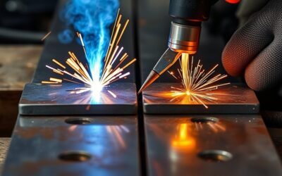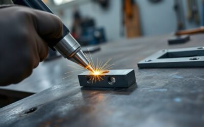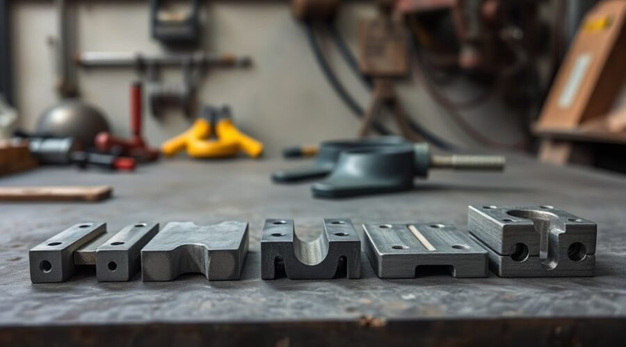
Weld joint types describe how two or more pieces of metal are positioned before welding. The five basic joint designs—butt, lap, tee, corner, and edge—cover most common fabrication layouts. Choosing the right joint depends on the load path, material thickness, fit-up, weld access, corrosion exposure, and the code or welding procedure that applies to the job.
Quick Answer
The five basic weld joint types are butt, lap, tee, corner, and edge joints. Butt joints place parts in the same plane, lap joints overlap them, tee joints meet at about 90 degrees, corner joints form an L-shaped corner, and edge joints place parallel or nearly parallel edges together.
Key Takeaways
- The five basic weld joint designs are butt, lap, tee, corner, and edge joints.
- Joint type describes part geometry; weld type describes the weld placed in that joint, such as a fillet or groove weld.
- Butt joints are common when a flush, in-line connection is needed, while lap joints use overlapping surfaces.
- Tee and corner joints commonly handle right-angle connections in frames, boxes, stiffeners, and structural assemblies.
- Edge joints are generally better suited to light-duty or low-stress applications than heavily loaded connections.
The 5 Basic Weld Joint Types
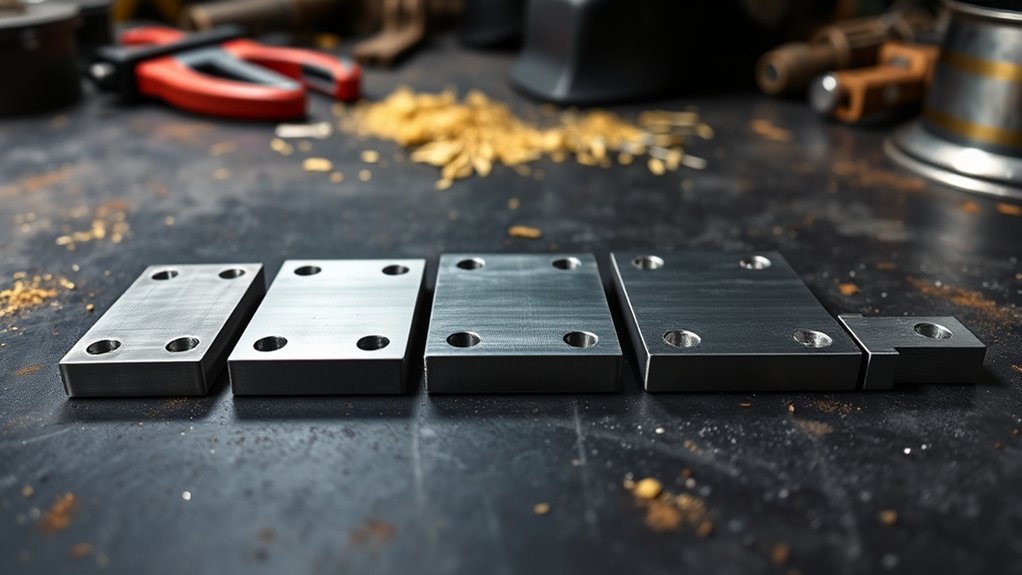
The five basic weld joint types are butt, lap, tee, corner, and edge. The American Welding Society has long used these joint names in welding-symbol references, and current welding education resources continue to teach the same five basic geometries. The latest AWS A3.0M/A3.0:2025 terminology standard is the current reference for standardized welding terms.
Note: A joint type is the arrangement of the parts before welding. A weld type is the deposited weld used to join them. For example, a tee joint often uses a fillet weld, while a butt joint commonly uses a groove weld.
| Joint | Geometry | Common Welds | Typical Uses | Main Considerations |
|---|---|---|---|---|
| Butt | Members meet in the same plane | Square or prepared groove welds | Pipe, plate, tubing, flush seams | Root opening, edge preparation, penetration, distortion |
| Lap | Surfaces overlap | Usually fillet welds | Sheet, plate, patches, brackets | Overlap length, fit-up, crevice corrosion, distortion |
| Tee | One member meets another at about 90° | Fillet or groove welds | Stiffeners, frames, structural members | Load direction, throat size, access, restraint |
| Corner | Members meet to form an L-shaped corner | Fillet or groove welds | Boxes, frames, enclosures, tanks | Open vs. closed fit-up, burn-through, angular distortion |
| Edge | Edges of parallel or nearly parallel members are joined | Edge or groove welds | Light-gauge seams and low-load details | Limited penetration and lower suitability for heavy impact or stress |
Butt joints align parts in one plane and are common in pipelines, tubing, plate work, and structural assemblies. Lap joints overlap two members and are useful where a flush surface is unnecessary. Tee and corner joints create right-angle connections, while edge joints join parallel or nearly parallel edges. Across all five forms, weld selection, fit-up, heat input, and service loading affect distortion and integrity. Understanding material thickness and TIG welder capability can also help when choosing equipment after the joint design has been established.
Butt Joint Welding for Strong Seams
Butt joints place two workpieces in the same plane so their edges meet or are separated by a specified root opening. They are widely used for plate, pipe, tubing, and other work where a relatively smooth, in-line connection is useful.
Common butt-joint preparations include square grooves, single-V or double-V grooves, single-bevel or double-bevel grooves, and other prepared grooves. The correct preparation depends on thickness, access, welding process, required penetration, and the applicable procedure or code. Edge preparation and fit-up matter because an incorrect root opening, poor alignment, contamination, or unsuitable parameters can contribute to incomplete fusion, incomplete joint penetration, porosity, burn-through, or excess distortion.
Butt joints can be welded with MIG/GMAW, TIG/GTAW, stick/SMAW, flux-cored, submerged arc, and other processes when the material, thickness, position, and qualified procedure permit. Heat input should be controlled according to the material and procedure: too little may produce inadequate fusion, while excessive heat can increase distortion or alter the heat-affected zone.
When designed and welded correctly, a butt joint can provide a direct load path and a strong, unobstructed seam. For beginners, understanding the relationship between process choice and heat control helps explain why the same joint may be welded differently on thin sheet, heavy plate, or pipe.
Pro Tip: Do not choose a groove angle or root gap from a generic chart when the work is governed by a welding procedure specification (WPS), code, drawing, or engineer-approved detail. Use the specified joint preparation and tolerances.
How Tee, Corner, and Lap Joints Work
Tee, corner, and lap joints expand welding options beyond in-line seams. Tee joints place one member against another at about 90 degrees. Corner joints form an L-shaped outside or inside corner. Lap joints overlap two surfaces. These layouts are common in frames, boxes, brackets, stiffeners, sheet-metal work, and structural fabrication. A multi-process welder may be useful when the fabrication job calls for more than one welding process, but the joint geometry should still be chosen from the design requirements first.
| Joint | Function | Typical Risk to Control |
|---|---|---|
| Tee | 90-degree intersection | Unequal fusion, restraint, distortion, lamellar tearing in susceptible plate/details |
| Corner | L-shaped assembly | Angular distortion, burn-through on thin material, lamellar tearing in susceptible restrained plate/details |
| Lap | Overlapping connection | Gaps, distortion, trapped contaminants, crevice corrosion |
| Risk | Distortion and weld discontinuities can affect any joint | Control fit-up, sequence, heat input, cleaning, and inspection |
Tee Joints
A tee joint is created when the edge of one member meets the surface of another at roughly a right angle. Fillet welds are common, but groove preparations may be specified when greater penetration is required. Welding from both sides can improve balance and capacity when the design calls for it. However, thick restrained plate can develop high through-thickness strain. TWI notes that lamellar tearing is particularly associated with joints such as T-joints and corner joints when susceptible rolled plate, restraint, and through-thickness strain are present.
Corner Joints
Corner joints form an L-shaped connection and may be open or closed depending on how the edges meet. They are common in boxes, frames, tanks, and enclosures. Fillet or groove welds may be used. Thin material is vulnerable to burn-through, while heat shrinkage can pull the angle out of square. Fixtures, tack placement, balanced welding, and a suitable sequence can help manage distortion.
Lap Joints
Lap joints join overlapping surfaces and commonly use fillet welds. They work well for sheet, plate, patches, and parts of unequal thickness because the amount of overlap can be adjusted to suit the design. The overlap should fit closely where required by the procedure. Unlike the earlier draft claim, lamellar tearing is not a characteristic lap-joint defect; a more typical concern is that the overlap can trap moisture or contaminants and create a crevice where corrosion develops if the design, sealing, coating, or drainage is poor.
Edge Joint Welding for Thin Metal Parts
Edge joints place the edges of two parallel or nearly parallel members next to each other and weld along those edges. They are frequently used on thin metal parts, light-gauge seams, flanges, and closures where the joint will not carry severe impact or high structural stress.
MIG/GMAW and TIG/GTAW can both be used on edge joints, but there is no universal rule that they are always the best choices. The correct process depends on the base metal, thickness, joint access, position, required quality, production rate, and applicable WPS. Proper fit-up is especially important on thin material because a large gap can increase the risk of burn-through or an inconsistent bead.
Edge joints can use square, V-, J-, or U-type preparations depending on the material and design, although the available joint penetration can be limited compared with other joint configurations. That is why edge joints are generally not the first choice for highly stressed or impact-loaded primary connections.
When TIG is selected, machine features should match the metal being welded; for example, AC capability is commonly relevant to conventional TIG welding of aluminum, while DC is commonly used for steels and many other metals. This makes AC/DC TIG welder capability an equipment consideration rather than a rule for choosing the edge-joint geometry itself.
How to Choose the Right Joint
Selecting the right weld joint depends on material thickness and type, loading conditions, required strength, access for welding, distortion control, corrosion exposure, inspection needs, and the governing drawing, code, or procedure. Effective weld-joint design matches the geometry to both service demands and fabrication limits.
- Define the load path. Identify whether the connection sees tension, compression, shear, bending, torsion, impact, or cyclic loading.
- Check the material and thickness. These affect edge preparation, preheat requirements, heat input, filler selection, and susceptibility to distortion or cracking.
- Review access. Confirm the welder or welding system can reach the joint, maintain the required angle, and weld the specified side or sides.
- Choose the required weld type and penetration. A butt joint may use a groove weld for a flush, high-integrity seam; tee, lap, and corner joints often use fillet welds, but the drawing or WPS controls.
- Account for fabrication risks. Thin butt or corner joints can burn through; heavily restrained T- or corner-type details in susceptible plate can face lamellar-tearing risk; lap joints can create corrosion-prone crevices.
- Confirm the code and WPS. Structural, pressure, piping, vehicle, and production work may have specific joint details, qualification rules, acceptance criteria, and inspection requirements.
Equipment capacity matters after the joint and weld requirements are known. For example, duty cycle can affect whether a welder can sustain the required production workload, but it does not determine which joint geometry is structurally correct.
Common Weld-Joint Problems and How to Reduce Them
| Problem | Where It May Appear | Typical Controls |
|---|---|---|
| Incomplete fusion or penetration | Butt, tee, corner, edge | Correct preparation, fit-up, parameters, work angle, travel speed, cleaning |
| Burn-through | Thin butt, corner, lap, or edge joints | Control gap and heat input; use suitable travel speed and backing when specified |
| Distortion | All joint types | Fixtures, balanced welds, tack sequence, controlled heat input, planned weld sequence |
| Lamellar tearing | Primarily restrained T-, corner-, and cruciform-type details in susceptible rolled plate | Reduce through-thickness strain, use suitable joint design/material, balanced welding, appropriate consumables and procedures |
| Crevice corrosion | Lap joints and other moisture-trapping details | Design for drainage/sealing, clean surfaces, apply suitable corrosion protection |
Warning: Welding can expose you to arc radiation, hot metal, electrical hazards, fire, fumes, and gases. Use suitable eye/face protection, protective clothing, ventilation or fume controls, and fire-prevention measures. Follow the applicable safety rules and your equipment instructions. See OSHA welding hazards and solutions and ANSI Z49.1:2021.
Frequently Asked Questions
What Are the 5 Basic Types of Weld Joints?
The five basic weld joint types are butt, corner, edge, lap, and tee joints. These terms describe how the workpieces are arranged before welding. The final weld may be a groove, fillet, edge, plug, slot, or another weld type depending on the joint, design, and procedure.
What Are the Types of Joints in Welding?
The basic welding-joint geometries are butt, lap, tee, corner, and edge joints. Joint design affects fit-up, access, load transfer, distortion, inspection, and the weld type that can be used. The applicable drawing, code, or WPS should define the actual preparation and acceptance requirements for production work.
What Are the Five Types of Welding?
There is no single authoritative rule that limits welding to exactly five processes. AWS recognizes many welding processes and process families. Five common arc-welding processes are SMAW (stick), GMAW (MIG), GTAW (TIG), FCAW (flux-cored), and SAW (submerged arc). Other recognized families include resistance welding, oxyfuel welding, high-energy-beam welding, and solid-state welding.
What Are Three Types of Welded Joints: 1, 2, 3?
Three common welded-joint types are 1) butt joints, 2) lap joints, and 3) tee joints. Butt joints commonly use groove welds; lap joints commonly use fillet welds; tee joints often use fillet welds but may use groove preparations when the design requires them. Corner and edge joints complete the traditional five basic joint types.
What Is the Difference Between a Weld Joint and a Weld Type?
A weld joint describes the arrangement of the workpieces, such as a butt or tee joint. A weld type describes the weld itself, such as a fillet or groove weld. One joint geometry can sometimes accept more than one weld type depending on the design.
Conclusion
The five basic joint designs—butt, lap, tee, corner, and edge—look simple, but each changes fit-up, load transfer, weld access, distortion, and inspection. Butt joints support in-line seams; lap joints provide overlap; tee and corner joints create right-angle connections; and edge joints suit lighter-duty parallel-edge details. Proper joint selection starts with the drawing, load path, material, service conditions, and applicable WPS or code—not with the welding machine alone.
Sources
- American Welding Society — AWS A3.0M/A3.0:2025 — current standardized welding terminology.
- Miller — Guide to the 5 Basic Types of Weld Joints — joint geometry, common preparations, applications, and limitations.
- TWI — Defects: Lamellar Tearing — conditions, susceptible joint designs, and prevention principles.
- OSHA — Welding, Cutting, and Brazing: Hazards and Solutions — welding health and safety hazards and controls.
- ANSI Z49.1:2021 — Safety in Welding, Cutting, and Allied Processes — PPE, ventilation, fire prevention, and general welding safety.