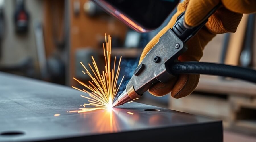
Flux core welding can produce strong, clean joints, but the result depends on matching the wire, machine setup, joint preparation, and technique. Wire feed speed, voltage, polarity, travel angle, work angle, and electrode stickout all affect how the puddle behaves. Small setup errors can cause porosity, excess spatter, lack of fusion, undercut, or trapped slag, so start with the wire manufacturer’s recommendations and tune the process from there.
Quick Answer
To get stronger, cleaner flux core welds, use the polarity and parameters specified for your exact wire, clean and fit the joint properly, use the correct drive roll, keep stickout within the recommended range, and drag the gun at roughly a 5–15° travel angle. Remove slag between passes and tune settings on scrap first.
Key Takeaways
- Match polarity, voltage, wire feed speed, drive rolls, and contact tip to the exact flux-cored wire and base-metal thickness.
- A common starting point for hobby self-shielded FCAW is about 3/4-inch stickout, but the electrode data sheet takes priority.
- Use a drag or pull technique with roughly a 5–15° travel angle under normal conditions; work angle depends on the joint.
- Clean the weld zone and the work-clamp contact area, and prepare thicker butt joints as required for full fusion.
- Remove slag completely between passes and troubleshoot defects by changing one variable at a time.
- Do not judge a critical weld only by appearance; structural work may require a qualified welding procedure and formal inspection.
At a Glance
| Time Required | About 10–15 minutes for setup and test beads; welding time depends on joint length and thickness. |
| Difficulty | Beginner to intermediate; vertical and overhead welds require more practice. |
| Tools Needed | FCAW-capable welder, correct flux-cored wire and contact tip, suitable drive roll, work clamp, wire brush or grinder, chipping hammer, pliers, and welding PPE. |
| Cost | Varies by wire, consumables, PPE, and whether you already own an FCAW-capable welder. |
Warning: Arc welding exposes you to intense UV radiation, hot metal, sparks, electrical hazards, and welding fumes. Wear a welding helmet with the correct filter shade, safety glasses, leather gloves, flame-resistant clothing, and suitable footwear. Remove combustible materials and provide effective ventilation or local exhaust. Do not weld coated, plated, painted, or unknown metal until its hazards are identified, and do not weld in a confined space without the required ventilation and safety controls. See OSHA 29 CFR 1910.252 for welding safety requirements.
Set Up Flux Core Welding for Stronger Beads
Proper setup is essential for stronger flux core welds. Before striking an arc, identify the exact wire classification, diameter, shielding method, required polarity, and recommended parameter range. The settings printed inside a welder or on the wire data sheet are starting points; final settings may need fine adjustment on scrap of the same material and thickness.
Know Whether the Wire Is Self-Shielded or Gas-Shielded
Flux-Cored Arc Welding has two main forms. Self-shielded FCAW (FCAW-S) creates its shielding from ingredients inside the tubular wire and does not require an external gas cylinder. Gas-shielded FCAW (FCAW-G) uses a flux-cored wire plus an external shielding gas. Miller explains both forms in its flux-cored welding basics guide.
This distinction matters because gas requirements and polarity are not interchangeable. For example, Hobart Fabshield 21B E71T-11 is a self-shielded wire specified for DCEN, while common gas-shielded T-1 wires are normally used on DCEP. Always follow the exact electrode manufacturer’s data sheet instead of applying one polarity rule to every flux-cored wire.
Note: If a machine was previously set up for solid-wire MIG, verify polarity before loading self-shielded flux-cored wire. A polarity mismatch can create an unstable arc, excessive spatter, poor bead shape, and inadequate fusion.
Match the Wire, Drive Rolls, and Contact Tip
Flux-cored wire should pass through drive rolls sized for its diameter. Knurled rolls are commonly used because the tubular wire is softer than solid MIG wire and can be deformed by excessive pressure. Set only enough drive-roll tension to feed reliably without crushing the wire.
Inspect the gun liner, contact tip, cables, and connections before welding. Replace a worn contact tip and remove heavy spatter from the gun. The contact tip must match the wire diameter, and the wire should feed smoothly without slipping or birdnesting.
Wire diameter should also suit the welder and material thickness. Common hobby sizes such as .030 and .035 inch cover many mild-steel jobs, while larger wire is generally used where the machine and application require greater deposition and heat input. For additional wire choices, see these flux core welding wire options.
Clean the Joint and Work-Clamp Area
Flux core tolerates some mill scale and contamination better than solid-wire MIG, but cleaner steel still gives the process a better chance of producing sound fusion. Remove oil, grease, heavy rust, loose scale, paint, moisture, and other contaminants from the weld zone whenever practical.
Clean the area where the work clamp contacts the metal as well. A poor clamp connection adds electrical resistance and can make the arc inconsistent.
Use the Right Flux Core Technique
Good flux core technique combines the correct travel direction, travel angle, work angle, stickout, and travel speed. These variables interact, so avoid changing several at once while troubleshooting. If you are still choosing equipment, understanding the capabilities of beginner-friendly welders and welding processes can also help match the machine to the job.
Drag Angle Control
For normal flux-cored welding, use a drag or pull technique. Point the gun back toward the weld puddle while moving away from the completed bead. Miller recommends a normal travel angle of approximately 5 to 15 degrees. Excessively steep travel angles can increase spatter, reduce penetration, and make the arc less stable.
Do not confuse travel angle with work angle. Travel angle describes how far the gun leans in the direction of travel. Work angle describes how the gun is aimed across the joint.
- For a flat butt joint, a work angle close to 90° to the plate surface directs the wire into the joint.
- For a 90° T-joint fillet weld, start near a 45° work angle so the arc is shared between both pieces.
- For a lap joint, aim the arc so enough heat reaches both the edge of the upper plate and the lower plate.
Stick-Out Length
Electrode stickout is the unmelted wire extending beyond the contact tip. About 3/4 inch is a common starting point for general hobby flux-cored welding, according to Miller, but the correct contact-tip-to-work distance or electrode extension depends on the specific wire and procedure.
Do not treat 1-1/4 inches as a universal maximum. Some industrial flux-cored electrodes are designed for longer extensions, while smaller hobby wire may run better closer to the common 3/4-inch starting point. Check the spool label, manufacturer’s data sheet, or qualified welding procedure.
Keep the extension reasonably constant while moving along the joint. Large changes in stickout change electrical resistance and heat in the wire, which can alter current, arc behavior, penetration, and bead shape.
Travel Speed Balance
There is no single travel speed, such as 6–12 inches per minute, that works for every flux core weld. Correct speed depends on wire size, voltage, wire feed speed, material thickness, joint design, position, and desired bead size.
Watch the relationship between the arc and puddle. If you travel too fast, the bead can become narrow and underfilled and may develop undercut or lack of fusion. If you move too slowly, the puddle can become overly wide or convex and slag may move ahead of the arc.
Use the welder or wire manufacturer’s chart as the initial setting, make a test bead on matching scrap, and adjust one variable at a time.
Pro Tip: Before welding the actual part, make two or three short test beads on scrap of the same alloy and thickness. Change only one setting between tests. This makes it much easier to see whether voltage, wire feed speed, stickout, or travel speed caused the improvement.
Drag the Gun for Cleaner Welds
Dragging the welding gun helps keep the arc ahead of the slag and allows the slag to trail behind the molten weld pool. This is why the common FCAW reminder is essentially: if the process leaves slag, drag the gun.
A modest 5–15° travel angle keeps the gun close to perpendicular while still providing a clear drag direction. Excessive backward lean can increase spatter and reduce penetration rather than improve it.
For ordinary flux-cored welding, a small drag angle gives better slag control than an exaggerated gun angle.
Welding position also changes technique. Vertical-up travel can provide better penetration on thicker material, while vertical-down travel may be useful on thinner material where burn-through is a concern. Overhead FCAW is more difficult and normally requires tighter puddle control and reduced parameters. Follow the wire manufacturer’s position limitations because not every electrode is approved for every position.
If you also use solid-wire MIG, remember that its shielding-gas recommendations are a separate topic. A MIG shielding gas guide should not be used as a universal gas specification for FCAW-G. Flux-cored gas requirements must match the wire data sheet.
Set Penetration-Boosting Flux Core Settings
Penetration depends on the complete welding system rather than one “hotter” setting. Wire feed speed, voltage, polarity, electrode extension, travel speed, joint preparation, welding position, and electrode type all interact.
Start with the voltage and wire feed speed recommended for the wire diameter and metal thickness. Wire feed speed largely determines welding current on a constant-voltage wire-feed machine, while voltage affects arc length and bead profile. Fine-tune both together rather than assuming that more voltage automatically gives a stronger weld.
Prepare the Joint for Fusion
Joint design becomes more important as material gets thicker. Miller recommends considering edge preparation on butt joints above roughly 1/4 inch so the weld can reach the root and fuse both sides of the joint. The exact groove angle, root opening, backing, and number of passes depend on the application or WPS.
Good fit-up also matters. A changing gap can force the welder to constantly alter travel speed and puddle size, making consistent fusion harder to maintain.
Use the Correct Polarity
Do not select DCEN simply because the process is flux core. Many common self-shielded wires use DCEN, while many gas-shielded flux-cored wires use DCEP. The correct choice is the polarity printed on the electrode package or manufacturer’s data sheet.
Understanding how multi-process welders switch between welding modes and polarity can be useful, but always verify the actual terminal configuration before welding.
Preheat Only When the Procedure Requires It
Preheating is not a generic trick for forcing deeper penetration. It is used when material composition, thickness, hydrogen control, cooling rate, code requirements, or a welding procedure calls for it. Miller notes that required preheat temperatures depend on the base material and welding procedure. See its preheat guidance.
For critical structures, high-strength steels, or unfamiliar alloys, follow an approved WPS or material manufacturer’s requirements rather than choosing a preheat temperature by guesswork.
Prevent Porosity, Spatter, and Slag
Porosity, spatter, and slag inclusions can have several causes, so diagnose them systematically. Base-metal contamination, improper polarity, unstable wire feeding, incorrect voltage-to-wire-feed relationship, excessive gun angle, poor stickout control, and inadequate interpass cleaning can all contribute.
For FCAW-G, shielding-gas problems add another group of possible causes, including leaks, drafts, contaminated gas, poor nozzle condition, or incorrect flow. Self-shielded FCAW does not use an external shielding-gas regulator.
Clean Base Metal
A properly prepared surface promotes a stable arc and sound fusion. Remove oil, grease, moisture, paint, heavy rust, dirt, and loose scale where practical. A wire brush or grinder can be used where appropriate, but protect yourself from grinding debris and from hazardous coatings.
| Action | Why It Helps |
|---|---|
| Clean the weld zone | Reduces contamination, porosity risk, and erratic arc behavior. |
| Clean the work-clamp location | Improves electrical continuity. |
| Remove slag between passes | Reduces the chance of trapping slag under the next bead. |
| Inspect wire and contact tip | Helps maintain steady wire feeding and current transfer. |
Between passes, remove the slag with a chipping hammer and wire brush until clean metal is exposed. Pay particular attention to bead toes and corners where slag can remain hidden before the next pass.
Control Voltage And Angle
Voltage and gun angle affect bead shape and arc stability, but troubleshoot them together with wire feed speed, stickout, travel speed, polarity, and consumable condition.
Do not assume that all spatter means voltage is too high. Miller notes that low voltage can also create excessive spatter with flux-cored and metal-cored wires. If spatter increases, compare the current settings with the manufacturer’s recommended range and check polarity, wire condition, stickout, contact-tip condition, and base-metal cleanliness.
If worm tracks or other unusual surface marks appear, first check the wire manufacturer’s troubleshooting guidance. Moisture, voltage, electrode extension, and gas coverage on FCAW-G can all play a role. Avoid making large voltage changes without checking the rest of the setup.
For machines that can switch between gas MIG and flux core, equipment differences may be relevant; this Hobart Handler 140 vs. Lincoln 140 comparison covers two common wire-feed welders.
Troubleshoot Common Flux Core Weld Defects
| Problem | Check First | Typical Correction |
|---|---|---|
| Excessive spatter | Polarity, voltage/WFS balance, stickout, dirty wire or metal, worn tip | Return to manufacturer settings and adjust one variable at a time. |
| Porosity | Contamination, moisture, excessive gun angle; gas leaks/drafts on FCAW-G | Clean and dry the joint; verify shielding system and electrode extension. |
| Slag inclusions | Pushing instead of dragging, poor interpass cleaning, slag running ahead of arc | Drag the gun, clean every pass, and correct travel speed/angle. |
| Lack of fusion | Insufficient heat, wrong angle, excessive travel speed, poor joint prep | Correct parameters and keep the arc directed into the joint and bead toes. |
| Burn-through | Too much heat for thin material or travel too slow | Reduce heat input or increase travel speed within the recommended procedure. |
| Undercut | Travel speed, excessive voltage, poor angle, failure to pause at the toe | Retune parameters and improve puddle placement. |
| Erratic wire feeding | Drive-roll size/tension, liner, contact tip, tangled spool | Correct the feed path before changing weld parameters. |
Avoid Common Flux Core Welding Mistakes
Common flux core welding errors usually trace back to setup, preparation, or handling variables. Before striking an arc, verify the wire classification, polarity, drive-roll setup, wire feed speed, voltage, electrode extension, work-clamp connection, and material preparation.
- Do not assume all flux-cored wires use the same polarity.
- Do not use an exaggerated travel angle when a small 5–15° drag angle is appropriate.
- Do not use one stickout value for every electrode; check the wire data sheet.
- Do not weld over oil, moisture, heavy rust, paint, or unknown coatings without proper preparation and hazard controls.
- Do not bury slag under the next pass; chip and brush every layer clean.
- Do not change voltage, wire feed speed, travel speed, angle, and stickout simultaneously while troubleshooting.
Dragging is generally preferred for slag-producing flux-cored wires because it helps keep slag behind the arc. It should not be described as automatically producing a stronger weld than every possible push technique; actual weld strength depends on fusion, joint design, electrode, parameters, procedure, and workmanship.
For longer projects, machine output limits also matter. Understanding welding-machine duty cycle can help prevent unnecessary thermal shutdowns, although TIG-specific equipment recommendations are separate from FCAW technique.
Inspect the Weld Before You Finish
After the weld cools enough to handle safely, remove slag and inspect the bead for obvious defects. Look for reasonably consistent width and profile, tie-in at the toes, cracks, visible porosity, undercut, overlap, excessive spatter, and areas where slag may be trapped.
Irregular bead shape can point to unstable travel speed, changing stickout, poor work angle, incorrect settings, or wire-feeding problems. A burned edge or hole may indicate excessive heat input, while a tall rope-like bead can indicate that the weld is too cold for the joint or that travel technique needs correction.
Also inspect the surrounding heat-affected area for visible cracking, distortion, or burn-through. Clean away loose slag before deciding whether another pass is needed.
Note: A good-looking surface does not prove complete internal fusion or structural adequacy. Load-bearing, safety-critical, coded, pressure-containing, or commercial welds may require a qualified welding procedure, qualified personnel, and specified inspection or testing. The AWS B2.1/B2.1M specification covers welding procedure and performance qualification.
Machine capability and thickness range also affect whether a particular welder is suitable for the joint. This guide to welders for home use and thickness handling provides additional equipment context.
Frequently Asked Questions
How to Get a Clean Weld With Flux Core?
Start with the correct wire, polarity, voltage, and wire feed speed for the material. Clean the joint, maintain the specified stickout, drag the gun at roughly a 5–15° travel angle, and keep travel speed steady enough that slag stays behind the arc. Remove all slag before each additional pass.
Can You Get Good Welds With Flux Core?
Yes. Flux-cored welding is widely used for fabrication, repair, construction, and industrial work. The result depends on using an electrode suited to the application and following its specified polarity, parameters, position limits, joint preparation, and technique. Self-shielded FCAW is particularly useful outdoors because it does not rely on external shielding gas.
Why Are My Flux Core Welds so Bad?
Start by checking polarity, wire classification, voltage and wire feed speed, stickout, drive-roll setup, contact-tip condition, work-clamp contact, joint cleanliness, gun angle, and travel speed. If using gas-shielded FCAW, also check shielding gas, hoses, nozzle condition, and drafts. Change one variable at a time so you can identify the actual cause.
Is It Better to Push or Pull When Flux Core Welding?
Pulling or dragging is normally preferred for slag-producing flux-cored welding because it helps keep the slag behind the arc. For ordinary flat and horizontal work, use a modest travel angle rather than an exaggerated lean. Position-specific procedures can vary, so follow the electrode manufacturer’s directions for vertical and overhead welding.
Does All Flux Core Wire Use DCEN Polarity?
No. Many popular self-shielded wires, including E71T-11 products such as Hobart Fabshield 21B, use DCEN. Many gas-shielded T-1 flux-cored wires use DCEP. The correct polarity is the one specified by the manufacturer for the exact wire.
How Much Stickout Should I Use for Flux Core?
About 3/4 inch is a common general starting point for hobby flux-cored welding, but it is not a universal specification. Electrode extension varies with the wire and procedure, especially with industrial FCAW products. Check the spool label or manufacturer’s data sheet and keep the extension consistent while welding.
Conclusion
Strong, clean flux core welds come from matching the process to the wire rather than relying on one universal setting. Verify polarity and parameter ranges, clean and prepare the joint, maintain consistent stickout, use a modest drag angle, watch the puddle, and remove slag between passes. When a defect appears, change one variable at a time and compare the result on scrap. For structural or safety-critical work, follow the applicable WPS, code, and inspection requirements rather than relying on bead appearance alone.
Sources
- Miller — Flux-Cored Welding: The Basics for Mild Steel — FCAW-S/FCAW-G basics, preparation, drive rolls, stickout, settings, drag technique, angles, and welding positions.
- Hobart Brothers — Fabshield 21B Data Sheet — E71T-11 classification, self-shielded operation, DCEN polarity, and wire specifications.
- Hobart Brothers — Filler Metal Must-Knows for New Welders — flux-cored classifications and DCEP gas-shielded T-1 wire guidance.
- OSHA — 29 CFR 1910.252 Welding, Cutting, and Brazing — PPE, ventilation, hot-work, and welding safety requirements.
- Miller — Preheat in Welding — when preheat is required and why temperatures depend on material and procedure.
- American Welding Society — AWS B2.1/B2.1M:2026 — welding procedure and performance qualification requirements.