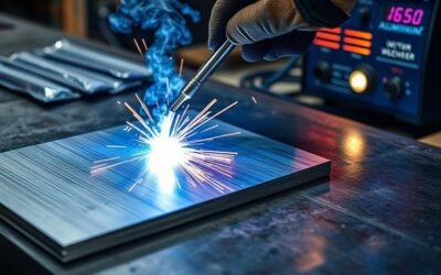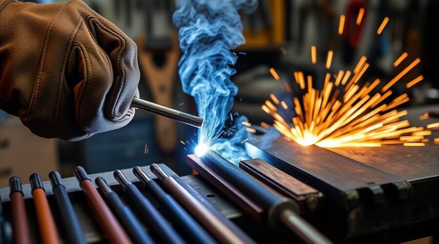
Stick welding works best when amperage, arc force, arc length, electrode angle, travel speed, and rod choice all match the joint and welding position. Arc force can help prevent sticking, but more is not automatically better. A short, controlled arc and the correct work and travel angles usually matter just as much as the machine setting. E6010, E6011, E6013, and E7018 also behave differently, so electrode selection should account for the power source, base metal, joint design, required penetration, and welding procedure.
Quick Answer
For most stick welding, start with the electrode manufacturer’s amperage range, use a short arc, and set the rod roughly 90° to a butt joint or 45° into a symmetrical fillet. Use about a 5–15° drag angle in flat, horizontal, and overhead welding, while vertical-up normally uses a slight push angle.
Key Takeaways
- Set amperage from the electrode manufacturer’s range first, then fine-tune in small increments while watching the puddle and finished bead.
- Arc force adds extra short-circuit current on machines that provide the feature; use enough to prevent sticking without making the arc unnecessarily harsh.
- Work angle comes from joint geometry: about 90° for a simple butt joint and about 45° into a symmetrical T-joint or fillet are common starting points.
- Flat, horizontal, and overhead SMAW commonly use a 5–15° drag angle; vertical-up normally uses a slight push or forehand angle.
- E6010 provides a forceful penetrating arc on DC, E6011 adds AC capability for many repair jobs, and E7018 is a low-hydrogen electrode used where weld quality and toughness are important.
- For structural, pressure-containing, coded, or safety-critical work, follow the approved welding procedure rather than generic internet settings.
Warning: Stick welding exposes you to electric shock, intense UV and infrared radiation, welding fumes, sparks, hot slag, and fire hazards. Wear an appropriate welding helmet over safety glasses, flame-resistant clothing, dry welding gloves, and suitable footwear. Provide effective ventilation, keep combustibles away, inspect cables and the electrode holder, and do not weld in confined spaces or on unknown containers without the required training and controls.
What Is Stick Welding Arc Control?
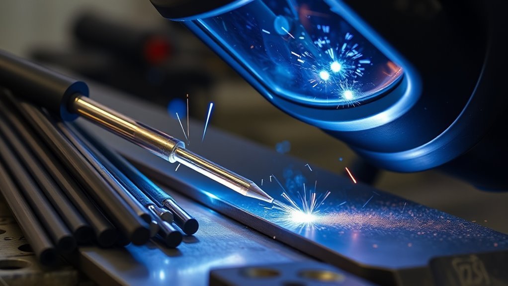
Arc control, often called arc force or dig, is a feature on many inverter and industrial stick welders. When the electrode gets very close to the puddle and arc voltage falls, the machine temporarily increases short-circuit current. That extra current helps keep the electrode from freezing to the work and changes how forcefully the arc drives into the joint.
Arc force is not the same as the main amperage setting. Amperage establishes the normal welding current, while arc force changes how strongly the machine reacts when the arc becomes very short.
Too little arc force can make some electrodes easier to stick or cause the arc to extinguish during tight manipulation. Too much can produce a harsh arc, more spatter, excessive puddle agitation, and poor control.
The best arc-force setting is usually the lowest setting that gives the electrode the arc drive and anti-sticking behavior the procedure requires.
Arc Force by Electrode Type
Arc-force settings should be matched to the electrode rather than selected only from material thickness. Cellulosic electrodes such as E6010 and E6011 often benefit from a crisper, more forceful arc, especially during root work. Low-hydrogen electrodes such as E7018 commonly run well with a softer arc.
Machine scales are not standardized. A setting of 30 on one welder may behave very differently from 30 on another, so use the machine manual and the puddle rather than copying a number from a different power source.
Pro Tip: If you do not know where to begin, start near the machine’s neutral/default arc-force setting. Increase it only if the rod repeatedly sticks or a cellulosic electrode needs more digging action; decrease it if the arc becomes unnecessarily violent or spattery.
Arc Force vs. Hot Start
Arc force and hot start solve different problems. Hot start briefly increases current when the arc is first struck to help establish the puddle. Arc force works while welding when the arc becomes very short. Some machines provide both controls, while others automate one or both.
How Do You Set Stick Welding Angle?
Stick welding uses two separate angles: work angle and travel angle. Work angle aims the electrode across the joint. Travel angle tilts the electrode forward or backward along the direction of welding.
For a simple butt joint, point the electrode approximately 90° to the work so the arc stays centered. For a symmetrical T-joint or fillet, aim about 45° into the corner so heat is shared between both members. These are starting points; unequal thickness, joint preparation, access, and puddle behavior may require adjustment.
Work Angle Basics
The work angle controls where the arc force and heat are directed across the joint. If it favors one side too heavily, one toe may fuse while the other remains cold.
- Butt or groove joint: normally center the electrode on the joint. A square butt joint commonly starts near 90° to the work surface.
- T-joint or inside fillet: approximately 45° into a symmetrical 90° corner is a common starting point.
- Unequal-thickness joint: a slight bias toward the thicker member may be useful when the approved procedure allows it.
- Horizontal fillet: a small upward bias can help counter gravity, but excessive bias can reduce fusion at the lower toe.
Work angle should therefore be based on the actual joint geometry, not simply on whether the weld is called 1G, 2G, 3G, 1F, 2F, or 3F.
Travel Angle Control
Travel angle is the fore-and-aft tilt of the rod. For flat, horizontal, and overhead stick welding, a 5–15° drag or backhand angle is a useful general starting point. Keep the angle small enough that the arc remains directed into the leading edge of the puddle rather than mostly into finished weld metal.
For vertical-up welding, a slight push or forehand angle is commonly used. Keep the puddle small and support it with controlled manipulation rather than increasing the angle excessively.
Vertical-down is a different technique. Only use it when the electrode, joint, material thickness, and applicable welding procedure allow downhill progression.
Position-Specific Adjustments
The following values are practical starting points, not substitutes for an electrode data sheet or welding procedure.
| Position / Joint | Work-Angle Starting Point | Travel-Angle Starting Point |
|---|---|---|
| 1G flat groove | Centered on the groove; about 90° on a simple square butt | 5–15° drag |
| 1F flat fillet | About 45° into a symmetrical corner | 5–15° drag |
| 2G horizontal groove | Centered in the groove, with minor bias as puddle control requires | Small drag angle |
| 2F horizontal fillet | Near 45° into the corner with slight upward bias if needed | 5–15° drag |
| 3G vertical-up groove | Centered on the groove | 0–15° push |
| 3F vertical-up fillet | Approximately split between both members | 0–15° push |
| 4G overhead groove | Centered on the groove | 5–15° drag |
| 4F overhead fillet | About 45° into a symmetrical corner | 5–15° drag |
For 5G and 6G pipe, both work and travel angles change continuously as the welder moves around the pipe. The correct technique also depends on whether the procedure uses E6010, E7018, another electrode, or a combination of root and fill electrodes.
How Long Should the Stick Welding Arc Be?
Arc length is the gap between the electrode tip and the weld puddle. As a general starting rule, keep the gap no longer than approximately the diameter of the electrode’s metal core. Some electrodes, especially low-hydrogen rods, perform best with an even tighter arc.
A long arc raises arc voltage and commonly causes excess spatter, undercut, a wide irregular bead, and possible porosity. An extremely short arc can make the rod stick or produce an overly crowned bead.
Because the electrode continuously burns shorter, the welder must keep feeding the holder toward the joint while maintaining the same gap.
Which Stick Welding Rod Should You Use?
Electrode selection should match the base metal, required weld-metal strength, power source, joint design, surface condition, welding position, service conditions, and applicable procedure. Position alone does not determine the best rod.
| Electrode | Typical Characteristics | Common Uses |
|---|---|---|
| E6010 | Forceful, deep-penetrating arc; all-position; commonly requires DC electrode positive | Pipe roots, open roots, repair work, and joints needing strong digging action |
| E6011 | Deep penetrating and all-position; commonly chosen when AC capability is useful | Maintenance, repair, outdoor work, and less-than-perfect surface conditions |
| E6013 | Softer arc, moderate penetration, relatively easy slag removal | Clean mild steel, sheet metal, light fabrication, and general-purpose work |
| E7018 | Low-hydrogen coating, smooth arc, medium penetration, strong and tough weld deposit | Structural work, heavy sections, low-alloy steels, and applications requiring low-hydrogen practice |
Even electrodes that tolerate scale or contamination should be used on properly prepared steel whenever practical. Remove excessive rust, oil, grease, moisture, paint, and loose scale before welding.
Electrode Type Selection
Start by identifying the base metal and required strength. AWS electrode classifications provide useful information. For common carbon-steel SMAW electrodes, the first two digits indicate minimum weld-metal tensile strength in thousands of psi, the next digit identifies usable welding positions, and the final digit relates to coating and suitable current characteristics.
Joint fit-up matters as well. A tight or un-beveled joint may need a more penetrating electrode, while thin material or a wide root opening may need a softer arc and smaller electrode to reduce burn-through.
For critical work, the welding procedure specification takes priority over a general electrode recommendation.
Rod Choice By Position
Many common E6010, E6011, and E7018 electrodes are classified for all-position welding, but usable diameter, amperage, puddle behavior, and procedure requirements can change with position.
- Flat: larger diameters and higher deposition rates are easier to manage because gravity supports the puddle.
- Horizontal: reduce puddle size as needed and use angle control to prevent the weld from sagging toward the lower plate.
- Vertical-up: smaller electrodes and lower current than flat-position settings are often easier to control.
- Overhead: keep the puddle small, maintain a tight arc, and use an electrode size and amperage that let the weld freeze quickly.
E6013 can be convenient for clean light-gauge work, but it is not automatically the “best” flat-position electrode. E7018 is widely used overhead when the procedure calls for it, but it is not automatically better than every other electrode simply because the weld is overhead.
How Do You Set Stick Welding Amperage?
Use the electrode manufacturer’s recommended current range as the starting point. Rod classification alone is not enough because amperage ranges vary by manufacturer, coating formulation, diameter, welding position, and product series.
For example, current ESAB E7018 products show different ranges for the same nominal diameter. Depending on the specific product, a 1/8-inch E7018 may be listed around 85–140 A, 90–160 A, or 110–140 A. That is why one universal 1/8-inch 7018 number should not be treated as a specification.
Once within the manufacturer’s range, adjust in small increments. If the rod repeatedly sticks and the arc is sluggish, current may be too low. If the puddle is uncontrollably fluid, undercut appears, or the electrode overheats, current may be excessive for the setup.
Note: Out-of-position welding often uses less current than the same electrode in the flat position, but there is no universal 10% reduction that applies to every rod, joint, and machine. Stay within the electrode manufacturer’s guidance and the approved procedure.
Stick Welding Angle Tips by Position
Angle control changes with position because gravity changes the way the molten puddle and slag move.
In flat welding, keep the work angle centered on the joint and use a small drag angle. In a horizontal fillet, keep the arc directed into the root and use only enough upward bias to prevent the puddle from washing downward.
For vertical-up welding, keep a short arc and use a slight push angle while allowing each portion of the puddle to freeze before moving farther upward. Overhead welding also needs a short arc and small puddle, with a modest drag angle rather than a steep rod tilt.
In 5G and 6G pipe positions, there is no single fixed angle for the entire joint. The welder continuously changes body position, work angle, and travel angle around the pipe while keeping the arc directed at the correct location in the puddle.
How Does Arc Force Change Weld Behavior?
Arc force changes how aggressively the machine responds when the electrode gets very close to the puddle. Increasing it generally increases short-circuit current, producing a crisper or more forceful arc and helping prevent the electrode from sticking.
Cellulosic rods such as E6010 or E6011 may benefit from more arc drive during root or manipulative welding. Low-hydrogen rods such as E7018 often favor a smoother, softer response.
Too little arc force can make the rod stick or cause the arc to drop out. Too much can increase spatter, disturb the puddle, and make bead control more difficult.
Do not use arc force as a substitute for correct amperage, arc length, fit-up, or electrode choice. If the basic setup is wrong, turning the arc-force control to an extreme usually creates a new problem rather than fixing the original one.
How Do You Prevent Spatter, Slag, and Porosity?
Spatter, slag inclusions, and porosity usually come from a combination of incorrect arc length, amperage, travel speed, angle, contamination, or poor interpass cleaning.
- Keep a short, stable arc rather than stretching it for a better view.
- Use amperage within the electrode manufacturer’s range.
- Keep the arc on the leading edge of the puddle.
- Use a modest travel angle so slag remains behind the arc instead of running ahead.
- Remove slag completely between passes.
- Clean oil, grease, moisture, loose rust, paint, and heavy scale from the joint when possible.
- Keep low-hydrogen electrodes dry according to their manufacturer’s storage instructions.
Stick Welding Troubleshooting Chart
| Symptom | Likely Causes | What to Check |
|---|---|---|
| Rod keeps sticking | Low current, excessively short arc, poor work connection, arc force too soft | Verify polarity, amperage, clamp connection, and arc-force setting |
| Excessive spatter | Long arc, excessive current, very high arc force, wrong polarity | Shorten the arc and confirm the electrode data sheet |
| Slag inclusion | Wrong angle, slag running ahead, poor cleaning, narrow joint access | Adjust angle/travel and clean thoroughly between passes |
| Porosity | Contamination, moisture, excessive arc length, damaged electrode coating | Clean the joint, use dry sound electrodes, and shorten the arc |
| Undercut | High current, long arc, excessive travel speed, poor manipulation | Reduce heat/arc length as appropriate and pause sufficiently at the toes |
| Lack of fusion | Low heat, excessive travel speed, incorrect work angle, poor preparation | Correct joint preparation, angle, current, and travel speed |
How Can You Improve Each Weld Pass?
A repeatable setup is more reliable than changing several controls at once. Use this sequence before judging the bead.
- Identify the base metal and joint. Confirm that the selected electrode is suitable for the material and required weld strength.
- Check polarity and current type. E6010, E6011, E7018, and other rods do not all have identical power-source requirements.
- Choose rod diameter. Match diameter to material thickness, joint access, position, and available amperage.
- Set amperage. Start within the manufacturer’s recommended range.
- Set arc force. Begin near neutral unless the electrode or machine manual suggests a different starting point.
- Clean the joint and work-clamp location. A poor electrical connection can make a good machine behave badly.
- Strike a practice bead when possible. Evaluate arc sound, puddle control, tie-in, bead profile, slag release, and spatter.
- Change one variable at a time. Adjust current in small steps before making another large change.
Between passes, remove slag completely and inspect the bead for undercut, trapped slag, porosity, incomplete fusion, cracking, or an excessively convex profile before depositing the next layer.
When Should You Use E6010, E6011, or 7018?
E6010 is commonly selected when a deep, forceful arc is needed, particularly for open-root pipe welding and applications where DC electrode-positive power is available. It can tolerate less-than-perfect surface conditions better than many softer-running electrodes, although cleaning is still preferred.
E6011 produces similar digging action and is widely used for maintenance and repair because AC operation is available with common E6011 products. It can be useful when an AC-only transformer welder is the available power source.
E7018 is chosen when low-hydrogen practice, strength, toughness, and a smooth weld profile are important. It is widely used in structural fabrication and other applications where hydrogen-assisted cracking must be controlled.
- Use E6010 when the procedure needs an aggressive, deep-penetrating DC arc.
- Use E6011 when penetrating action plus AC capability is valuable.
- Use E7018 when the procedure calls for low-hydrogen weld metal and suitable mechanical properties.
- Always match the electrode to the base metal, position, power source, joint, and required welding procedure.
How Should You Store 7018?
Low-hydrogen electrodes require moisture control. Once packaging is opened, storage and allowable atmospheric exposure depend on the exact electrode classification, manufacturer instructions, and applicable welding code or procedure.
Do not assume that every E7018 can be left open indefinitely or that one oven temperature applies to every product. Follow the manufacturer’s storage and re-drying instructions, especially for structural or code-controlled welding.
Stick Welding Tips for ESAB Machines
Many current ESAB inverter stick welders provide features such as adjustable Arc Force and Hot Start. Current examples include models in the Arc and Rogue families, but controls and available ranges vary by machine.
Begin by selecting the correct electrode polarity and amperage for the rod. Set Arc Force near the machine’s recommended starting point, then run a test bead. With an E6010 or E6011-type electrode, additional arc force may help if the arc repeatedly extinguishes or the rod sticks during tight manipulation. With E7018, a smoother arc-force setting is often easier to control.
Do not assume every ESAB machine uses the same numeric scale. Some models use percentages, some use simplified controls, and some automate more of the response. The exact operator manual takes priority over settings copied from another model.
Likewise, machine size and portability vary widely. ESAB sells small portable inverter machines as well as much larger industrial power sources, so statements about weight, controls, duty cycle, or output should be tied to the exact model.
Stick Welding Safety Basics
Good technique does not make unsafe welding acceptable. Before striking an arc:
- Wear safety glasses under a properly rated welding helmet.
- Cover exposed skin with flame-resistant clothing and use dry welding gloves.
- Use suitable boots and protect clothing openings from falling slag, especially overhead.
- Provide adequate general or local exhaust ventilation for welding fumes.
- Keep your head out of the fume plume when positioning yourself to see the puddle.
- Keep flammable materials away and provide appropriate fire protection.
- Inspect the electrode holder, cables, connectors, and work clamp before use.
- Do not weld while standing in water or with wet gloves or clothing.
- Treat coated, galvanized, stainless, painted, plated, or unknown metals as potential fume hazards requiring additional evaluation and controls.
- Use appropriate confined-space procedures; ordinary shop ventilation rules are not enough for tanks and enclosed spaces.
Frequently Asked Questions
What Is the Correct Rod Angle for Stick Welding?
The correct angle depends on joint geometry and position. A simple butt joint commonly starts with the rod centered at about 90° to the work, while a symmetrical T-joint fillet starts around 45° into the corner. Flat, horizontal, and overhead SMAW generally use a 5–15° drag angle; vertical-up normally uses a slight push angle.
Do You Run 7018 Uphill or Downhill?
E7018 is normally run vertical-up when a vertical groove or fillet weld requires full fusion and structural-quality deposition. Vertical-down use should only be performed when the specific electrode and approved procedure allow it. Keep a tight arc, control puddle size, and follow the applicable WPS on critical work.
What Are the Recommended Settings for a 1/8-Inch 7018 Stick Welder?
Check the exact electrode package first. Current ESAB 1/8-inch E7018 products show ranges such as approximately 85–140 A, 90–160 A, or 110–140 A depending on the product. Start within the manufacturer’s range and adjust for welding position, joint geometry, machine response, and puddle behavior rather than using one universal amperage number.
What Are Common Stick Welding Mistakes?
Common mistakes include using the wrong polarity, running too long an arc, selecting excessive or insufficient amperage, using the wrong work angle, traveling too fast or too slowly, failing to clean between passes, using damp or damaged electrodes, and trying to correct a poor setup with excessive arc force.
What Arc-Force Setting Should I Start With?
Start near the machine’s neutral or factory-recommended setting unless its manual or the procedure specifies otherwise. Increase arc force if a cellulosic rod needs more arc drive or repeatedly sticks during a short arc. Reduce it if the arc becomes harsh, excessively spattery, or difficult to control.
How Long Should the Arc Be When Stick Welding?
A practical starting point is an arc no longer than roughly the diameter of the electrode’s metal core. Many rods, including low-hydrogen electrodes, work well with an even tighter arc. A long arc tends to increase spatter, undercut, bead width, instability, and porosity risk.
Can You Weld Dirty Steel With E6010 or E6011?
E6010 and E6011 tolerate rust, scale, and contamination better than many softer-running electrodes, but that does not make surface preparation unnecessary. Remove excessive rust, grease, oil, moisture, paint, and loose scale whenever possible to improve fusion and reduce porosity and other defects.
Sources
- MillerWelds, Five Steps to Improving Your Stick Welding Technique — arc length, amperage adjustment, polarity, and travel-angle guidance.
- MillerWelds, 8 Questions About Stick Welding Rods Answered — E6010, E6011, E6013, E7018 classification, use, and storage guidance.
- Hobart Brothers, Basic Stick Welding — Electrode Technique — butt-joint, fillet-joint, arc-length, and travel-angle guidance.
- ESAB, current E7018 product data — manufacturer amperage ranges and low-hydrogen electrode specifications.
- Lincoln Electric equipment documentation — SMAW arc-force operation and electrode-dependent arc-control behavior.
- U.S. Occupational Safety and Health Administration, welding safety guidance — PPE, radiation, fumes, electrical, hot-metal, and fire hazards.
Conclusion
Consistent stick welding depends on more than amperage alone. Start with the correct electrode and polarity, stay within the manufacturer’s current range, maintain a short arc, and use work and travel angles that match the joint and welding position. Arc force can improve stability and prevent sticking, but excessive arc force can make the puddle harsh and spattery.
E6010 is useful when a strong digging DC arc is required, E6011 adds useful AC capability for many repair jobs, and E7018 is a low-hydrogen choice for applications where strength, toughness, and hydrogen control matter. On critical work, the approved welding procedure and electrode manufacturer’s data always take priority over generic settings.