Seam and spot resistance weld symbols carry specific instructions that shape how a joint is made and inspected. A centered circle, parallel lines, and related dimensions may seem simple, yet each detail changes weld size, spacing, and continuity. Misreading these marks can lead to costly fabrication errors. The next step is to separate spot from seam notation and identify the details that control the result.
Key Takeaways
- Resistance spot weld symbols use a centered circle, with diameter left of the symbol and pitch right of it.
- Parentheses above or below the symbol indicate the number of spot welds, not dimensions.
- Resistance seam weld symbols use two parallel lines for continuous or intermittent welds.
- For seam welds, size and shear strength appear left of the symbol, while length and pitch appear right.
- Flush contour symbols show a required smooth surface finish for both spot and seam resistance welds.
Resistance Spot and Seam Weld Symbols Explained
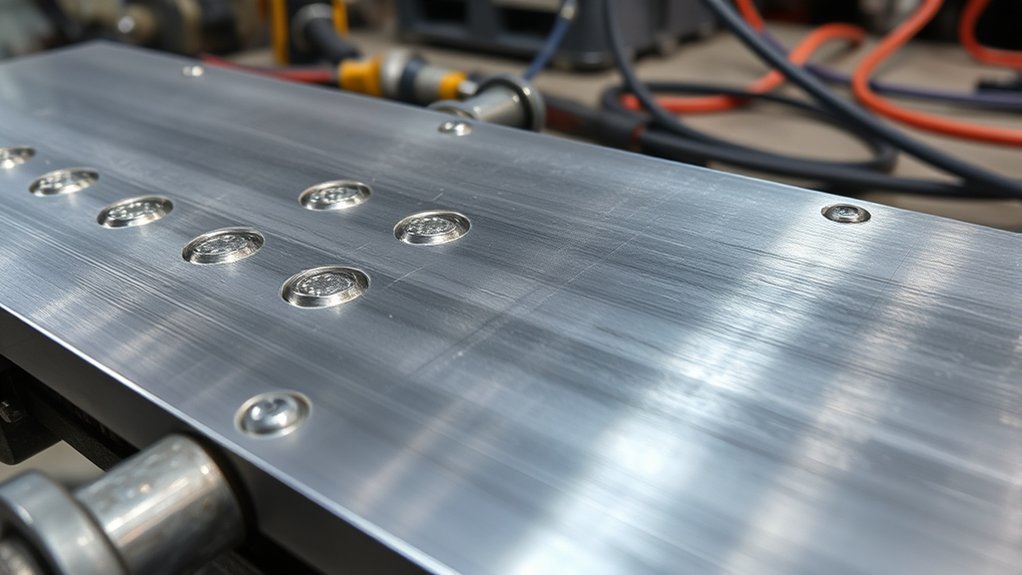
Resistance spot and seam weld symbols identify the weld type and its location on the reference line with clear, standardized notation.
Resistance spot weld symbols use a circle centered on the reference line, showing weld type without side bias and marking weld orientation by position alone. Their size dimensions appear to the left as a diameter dimension at the faying surface, while pitch and spacing may be placed to the right for controlled joint layout.
Resistance spot weld symbols use a centered circle, with size left and pitch or spacing right for controlled layout.
The seam weld symbol uses two parallel lines, with size dimensions and shear strength dimensions placed to the left; length, pitch, and spacing may extend to the right. A number of welds may be given in parentheses above or below either symbol.
A flush contour symbol, also above or below, indicates surface requirements for a liberated, finished joint. These symbols provide precise, compact instruction for fabrication, inspection, and disciplined weld execution, ensuring consistency in results for common welding tasks.
How to Read a Resistance Spot Weld Symbol
A resistance spot weld symbol is read from its placement on the reference line, where a centered circle indicates the weld type and no side significance. The weld symbol is interpreted with the reference line as the primary guide in resistance spot welding.
The size is placed to the left of the symbol and gives the diameter required at the faying surface. To the right, the pitch identifies the spacing pattern between spot welds. The number of spot welds, when required, appears in parentheses above or below the symbol, depending on location.
Supplementary symbols may accompany the weld symbol to state added requirements. A flush contour symbol, for example, calls for a smooth finished surface after welding. Understanding duty cycle is crucial for ensuring uninterrupted welding sessions, especially in demanding environments.
Each element is read in sequence, allowing a precise specification that reduces ambiguity and supports disciplined fabrication. This layout gives engineers and fabricators a clear path to compliance and control.
Spot Weld Size, Pitch, and Spacing
Spot weld dimensions are specified directly on the drawing to control both joint capacity and layout. On engineering drawings, spot weld size is given as the diameter at the faying surface, placed to the left of the weld symbol in fractions or decimals. The minimum acceptable shear strength, also left of the symbol, defines load resistance in pounds per spot. Pitch, shown to the right, states the distance between consecutive welds; spacing governs how far apart welds run along the seam. Both values may be listed in increments that preserve alignment and structural order. Understanding the importance of weld specifications is crucial for achieving high-quality results.
| Parameter | Location | Purpose |
|---|---|---|
| Diameter | Left of weld symbol | Size control |
| Pitch | Right of weld symbol | Repetition control |
| Spacing | Along seam | Integrity control |
Clear specification frees fabrication from guesswork. The number of spot welds, when stated, confirms total demand without ambiguity.
Spot Weld Count and Flush Symbols
Spot weld count is indicated in parentheses adjacent to the symbol, specifying the exact number of welds required for the joint. A flush contour symbol is added when a flush surface condition is required, making the finish requirement explicit in the drawing. The placement of the spot weld symbol relative to the reference line remains significant for interpreting the weld location and associated requirements. Understanding material thickness capacity is essential for ensuring the integrity of the weld in various applications.
Spot Weld Count
The required number of spot welds is shown in parentheses above or below the spot weld symbol, while the weld size is indicated by the circle diameter placed to the left of the symbol and the pitch by the spacing value to the right. This notation states the number of spot welds required with no ambiguity in specifications.
In resistance spot welding, the spot weld symbol is centered on the reference line when no side significance is assigned, supporting direct reading. The diameter of the weld identifies the required joint size at the faying surface, while the pitch of spot welds supplies spacing information for repeated welds.
If a flush surface requirement is needed, a flush contour symbol may be added, but the count remains governed by the parenthetical number and clear symbol placement.
Flush Symbol Placement
When a flush finish is required, the flush contour symbol is added to the resistance spot weld symbol to indicate that the finished surface should be flush after welding. The flush symbol is placed on the weld symbol to guide fabrication without ambiguity.
The diameter of each resistance spot weld is shown to the left of the reference line, while the number of welds is stated in parentheses above or below the symbol. Pitch and spacing are noted to the right, defining the distance between weld centers.
Centering the weld symbol on the reference line removes side significance, so placement remains neutral and clear. This arrangement supports disciplined interpretation, allowing workers to execute the joint efficiently and with confidence.
How to Read a Resistance Seam Weld Symbol
A resistance seam weld symbol is identified by two parallel lines on the reference line, indicating the weld’s continuous or intermittent character and length. The size, including weld width and minimum shear strength, is placed to the left of the symbol, while pitch for intermittent welds is placed to the right. Required weld count may appear in parentheses above or below the symbol, and a flush contour mark may be added when a flush surface is specified. Understanding these symbols is crucial for effective welding processes and equipment to ensure the quality and integrity of the welds.
Seam Weld Symbol Basics
Seam weld notation uses two parallel lines to represent a continuous resistance weld along a joint, with size and shear strength placed to the left of the symbol. The seam weld symbol is centered on the reference line, so side placement has no inherent meaning unless specified.
On drawing dimension lines, weld size is listed before shear strength, while the right side may carry length data. Pitch dimensions, if present, indicate spacing associated with intermittent welds and are separated by a hyphen.
Supplementary symbols may be attached to define contour requirements, including flush surfaces or smooth changes. The number of required seam welds may appear in parentheses above or below the weld symbol, depending on location.
This notation provides disciplined, readable control for liberated fabrication practice.
Reading Size And Pitch
The size of a resistance seam weld is read to the left of the weld symbol, where it identifies the width or diameter at the faying surface, while the pitch is read to the right, where it specifies the spacing between individual welds.
On a reference line, these dimensions remain on the same side as the weld symbol for clarity. The seam weld symbol uses two parallel lines, and related specifications may appear above or below it.
Length, contour, and the number of welds can be added in parentheses when required. This arrangement allows direct reading of size and pitch without confusion.
Precise placement supports accurate interpretation, enabling technicians to follow specifications and produce a resistance seam weld that meets the intended dimensions and width.
Seam Weld Length, Pitch, and Intermittent Runs
When specifying seam welds, the symbol’s right-hand notation defines the required run length, while intermittent arrangements use the same right side to show the pitch, or center-to-center spacing, between weld segments.
This side significance keeps resistance welds readable: the weld symbol sits on the reference line, with two parallel lines identifying a seam weld and the left side carrying size or shear strength and related dimensions.
For a continuous seam weld length, the notation states the total extent needed for joint integrity.
For intermittent runs, the pitch governs how segments are distributed along that length, and a number in parentheses may identify how many segments are required.
Such notation gives engineers a precise basis for specification, inspection, and fabrication, without ambiguity or dependence on assumptions.
The result is clear control of load transfer, joint continuity, and measured spacing across the weld path. Additionally, understanding optical clarity ratings can help ensure the appropriate helmet is selected for the specific welding task at hand.
Flush Contours and Other Seam Weld Details
A flush contour symbol added to a seam weld symbol indicates that the finished weld surface must be smooth and level with the base material where the joint meets.
In seam weld symbols, two parallel lines identify weld placement on the reference line, while dimensions define width and length with precision. For intermittent seams, pitch follows the length dimension to show spacing between individual welds.
The flush contour callout refines the surface finish requirement, directing a flat shift at the weld face. Such specifications support both functional integrity and aesthetic requirements, especially where exposed joints demand clean geometry.
The flush contour callout refines the surface finish, ensuring a flat weld face for both function and appearance.
The symbol set consequently communicates weld placement, extent, and finishing expectations without ambiguity. By combining contour, width, and pitch data, seam weld symbols provide a concise, liberated method for defining production intent and controlling the final condition of the joint. Additionally, understanding key features of top welding tables can enhance the overall welding process and project outcomes.
Common Mistakes in Weld Symbol Reading
Common errors in weld symbol reading often begin with misreading the reference line, since symbol placement can indicate side significance or the absence of it. A weld symbol must be read in relation to the reference line, or the design intent becomes distorted.
- Size and strength data, usually left of the weld symbol, are sometimes mistaken for dimensions only, producing undersized or excessive joints.
- For resistance spot welds, pitch and spacing appear to the right; reversing them shifts weld location and weakens load distribution.
- Parentheses may show welds quantity, not dimensions, while supplementary symbols govern contour requirements and finishing.
Precision in reading preserves autonomy from costly rework and inspection failures. Each mark on the drawing carries controlled meaning: placement, quantity, contour, and geometry. Additionally, understanding the 75/25 mix ideal for MIG welding on carbon steel can further enhance the effectiveness of your welds.
Careful interpretation of dimensions and supplementary symbols keeps fabrication aligned with specification, supports consistent quality, and prevents avoidable error in seam and spot resistance welds.
Frequently Asked Questions
How Do You Interpret Weld Symbols?
Weld symbols are interpreted by reading the arrow, reference line, and attached marks to identify weld joint types, size, location, and quantity.
Weld symbol basics guide interpreting welding drawings, while common welding terms clarify weld quality indicators, weld strength factors, and welding processes overview.
Essential welding tools support execution, and safety in welding remains critical.
Accurate reading improves effective communication in welding and supports precise, liberated fabrication choices.
What Is the Symbol for Spot Weld Welding?
The symbol for a spot weld is a circle placed on, above, or below the reference line. It identifies spot weld applications, spot weld design, and spot weld materials, while the notation also supports spot weld techniques, spot weld equipment, and spot weld benefits.
The diameter, count, and pitch guide spot weld strength and spot weld inspection. Proper spot weld safety matters, especially in spot weld vs. altre welding decisions.
What Are the Different Types of Seam Weld Symbols?
Seam weld symbols include continuous, intermittent, and contour variants—good fences make good neighbors—on the reference line. The continuous form marks weld joint types for welding process variations; intermittent forms add pitch for seam weld applications.
Size, length, and spacing address material thickness considerations and distortion control methods. Supplementary contours aid weld quality inspection, joint preparation techniques, filler material selection, heat input management, and welding safety practices.
What Do 1F, 2F, 3F, and 4F Mean in Welding?
1F, 2F, 3F, and 4F mean welding positions explained: flat, horizontal, vertical, and overhead, respectively.
In 1F welding techniques, the work is easiest; 2F joint designs demand more control.
3F weld applications challenge pool stability; 4F quality standards are strictest because gravity disrupts weld strength factors.
These welding equipment types, seam welding processes, spot weld advantages, and weld inspection methods guide safe, precise liberation through mastery of posture and technique.
Conclusion
In conclusion, resistance spot and seam weld symbols function as a precise language for fabrication, where size, pitch, length, count, and contour together define the required joint. Misreading even one element can alter weld performance and compliance. Like a map with a misplaced coordinate, a symbol interpreted incorrectly can lead a shop far from the intended result. Careful reading preserves consistency, reduces rework, and guarantees the weld matches the design intent.