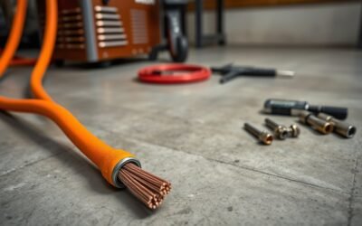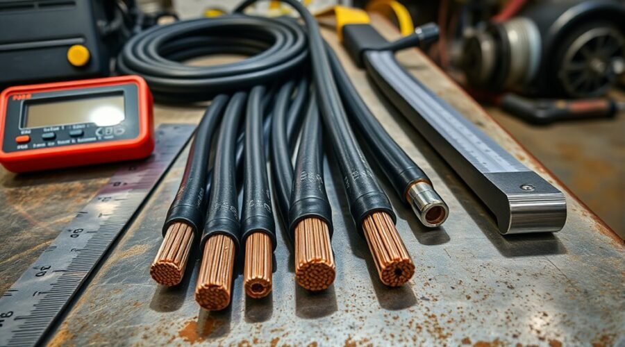
A welding cable size chart should match three things: the welding amperage, the duty cycle, and the total combined length of the electrode and work leads. Cable size cannot be chosen from amperage alone. Longer circuits need larger conductors to control resistance, voltage drop, and heating, while higher duty cycles put more continuous thermal load on the cable.
Quick Answer
Choose welding cable by the amperage you will weld at, duty cycle, and total combined length of the electrode and work leads. There is no universal amp rating for 1/0, 2/0, or 4/0 cable. Use the welder manufacturer’s selector table, then move to a larger conductor if the manual or operating conditions require it.
Key Takeaways
- Size welding leads by amperage, duty cycle, and total circuit length, not by amperage alone.
- Add the electrode lead and work lead together when using a welding cable size chart.
- Longer circuits usually require larger conductors because resistance and voltage drop increase with length.
- In AWG sizing, a lower number means a larger conductor until the aught sizes are reached; 4/0 is larger than 2/0 and 1/0.
- The welding machine manual and the cable manufacturer’s ratings take priority over a generic chart.
What Is Welding Cable Ampacity?
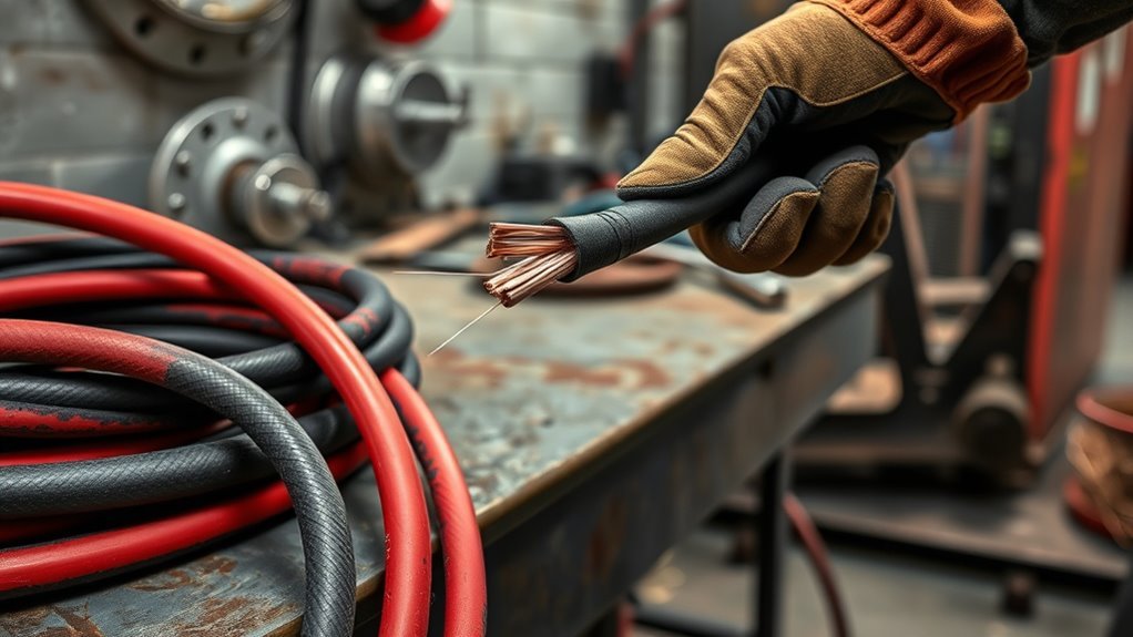
Welding cable ampacity is the amount of current a specific cable can carry under stated conditions without excessive conductor or insulation temperature. It is affected by conductor size, conductor material, insulation rating, duty cycle, installation conditions, and ambient temperature.
For welding leads, however, thermal ampacity is only part of the selection process. The cable also has to be large enough to keep resistance and voltage drop within the limits used by the welding-machine manufacturer. That is why the same welding current can require different cable sizes at different circuit lengths.
Do not treat an AWG size as having one universal welding-amp rating. A cable manufacturer’s product rating and the welding power source’s cable-selector table should be checked together.
Note: Welding output leads are different from the power cord or extension cord that supplies AC input power to the welder. Input-circuit wiring has separate sizing and code requirements.
How to Read a Welding Cable Size Chart
Read a welding cable size chart by starting with the welding current, then checking the duty cycle and the total combined length of both welding leads. Miller’s current cable-selector guidance uses this method and states that total cable length means the electrode cable plus the work cable.
For example, a 60-foot electrode lead and a 40-foot work lead make a 100-foot total welding circuit. If the power source is 100 feet from the work and both leads are approximately 100 feet long, the chart must be read as a 200-foot combined circuit.
Pro Tip: Measure both leads before choosing cable. One of the most common sizing mistakes is using only the one-way distance from the welder to the workpiece instead of adding the electrode and work leads together.
The following table is a practical copper welding-cable reference based on Miller’s published selector. It is a general guide, not a replacement for the manual supplied with your welding machine.
| Welding Amps | ≤100 ft 10–60% Duty |
≤100 ft 60–100% Duty |
150 ft | 200 ft | 250 ft | 300 ft | 350 ft | 400 ft |
|---|---|---|---|---|---|---|---|---|
| 100 A | 4 AWG | 4 AWG | 4 AWG | 3 AWG | 2 AWG | 1 AWG | 1/0 | 1/0 |
| 150 A | 3 AWG | 3 AWG | 2 AWG | 1 AWG | 1/0 | 2/0 | 3/0 | 3/0 |
| 200 A | 3 AWG | 2 AWG | 1 AWG | 1/0 | 2/0 | 3/0 | 4/0 | 4/0 |
| 250 A | 2 AWG | 1 AWG | 1/0 | 2/0 | 3/0 | 4/0 | 2 × 2/0 | 2 × 2/0 |
| 300 A | 1 AWG | 1/0 | 2/0 | 3/0 | 4/0 | 2 × 2/0 | 2 × 3/0 | 2 × 3/0 |
| 350 A | 1/0 | 2/0 | 3/0 | 4/0 | 2 × 2/0 | 2 × 3/0 | 2 × 3/0 | 2 × 4/0 |
| 400 A | 1/0 | 2/0 | 3/0 | 4/0 | 2 × 2/0 | 2 × 3/0 | 2 × 4/0 | 2 × 4/0 |
For the 150-foot and longer columns above, the manufacturer table applies its stated 10–100% duty-cycle guidance. At very high amperage and long distances, the table begins specifying parallel welding cables rather than one extremely large conductor.
A welding cable chart is only meaningful when amperage, duty cycle, and the combined length of both leads are known.
When to Use 1/0, 2/0, and 4/0 Cable
1/0, 2/0, and 4/0 welding cables do not have one fixed welding-amp limit. Their suitability changes with duty cycle and circuit length.
| Cable size | Where it commonly appears in a selector chart |
|---|---|
| 1/0 | Medium-to-high current on shorter circuits, or lower current on longer circuits. |
| 2/0 | Higher duty-cycle work, higher amperage, or increased circuit length. |
| 4/0 | High-output welding and long circuits where voltage drop becomes a major sizing factor. |
For example, the same 400 A application can call for 1/0, 2/0, 3/0, 4/0, or parallel conductors as duty cycle and total cable length change. This is why purchasing cable from a single “amps per gauge” number can lead to an undersized or unnecessarily heavy lead.
Why Cable Length Changes the Required Cable Size
Cable length does not simply make the conductor’s thermal ampacity disappear. Instead, longer cable has more electrical resistance. At welding currents of several hundred amps, even a small amount of added resistance can produce meaningful voltage drop and heat.
The practical result is that a cable that works well on a short welding circuit may be too small for the same amperage at 150, 200, or 300 feet of combined lead length.
Manufacturers therefore increase conductor size as total circuit length rises. This keeps more of the power source’s output available at the arc and reduces unnecessary cable heating.
How Voltage Drop Affects Weld Quality
Voltage drop occurs when current flows through the resistance of the electrode lead, work lead, connectors, clamps, and terminal connections. Excessive resistance reduces the voltage available at the welding arc and turns part of the electrical energy into heat.
The result may include an unstable arc, difficulty maintaining the intended welding parameters, excess cable heating, or reduced process performance. The exact effect depends on the welding process and power source.
Do not apply a universal “3% voltage drop” rule to welding output leads. Welding-equipment manufacturers publish their own sizing criteria. Miller’s selector, for example, states that its cable sizes are based on either a voltage drop of 4 volts or less or a minimum current-density criterion.
Voltage Drop Basics
| Condition | What happens | Typical response |
|---|---|---|
| Short circuit length | Lower conductor resistance | Use the size specified for the current and duty cycle |
| Longer circuit | More resistance and voltage drop | Move to a larger conductor as the selector requires |
| High welding current | More heat for a given resistance | Verify cable size, connections, and duty cycle |
| Loose or dirty connection | Localized resistance and heating | De-energize, clean, inspect, and secure the connection |
Weld Quality Impact
If the leads are undersized for the current and distance, cable resistance can change the electrical conditions at the arc. The operator may notice excessive cable heat, a less consistent arc, or difficulty achieving the expected output at the work.
- Long circuits often require larger conductors.
- Higher duty cycles increase cable heating.
- Loose connectors and work clamps add resistance.
- Damaged cable should not remain in service.
- Machine-specific recommendations take priority over generic charts.
How to Choose the Right Cable Gauge
Use this process to choose a welding cable gauge:
- Determine the highest welding current you plan to use. If the leads will remain on a machine that may be operated at full output, size them for that expected maximum use.
- Check the duty cycle. A higher duty cycle keeps current flowing for a greater portion of the rated time period and usually requires more thermal capacity.
- Add both lead lengths. Electrode lead plus work lead equals the total weld-circuit length used in the selector table.
- Find the required AWG size in the machine manual. Do not substitute a generic fixed amp rating when the manufacturer supplies a table.
- Verify the cable’s own markings and ratings. Confirm conductor material, temperature rating, voltage rating, and suitability for welding service.
- Inspect the completed setup under normal use. Excessive cable or connector heating is a reason to stop and investigate the cable size, connections, or application.
Note: AWG numbering runs backward through the numbered sizes: 2 AWG is larger than 4 AWG. After 1 AWG come 1/0, 2/0, 3/0, and 4/0, with each successive aught size becoming larger.
When to Move Up a Cable Size
Move to a larger welding cable when the manufacturer’s selector calls for it or when operating conditions increase electrical and thermal stress.
- Longer total cable length: More conductor length means more resistance and voltage drop.
- Higher duty cycle: Longer periods of current flow increase cable temperature.
- Higher welding current: Larger currents increase heating losses in the cable and connections.
- High ambient temperature: Follow the cable manufacturer’s temperature and derating instructions where applicable.
- Cable heating in service: Stop and investigate if a correctly connected cable becomes excessively hot.
- Manufacturer requirement: Always move up when the welding-machine manual specifies a larger conductor.
At very high output and long circuit lengths, a manufacturer may specify two or more cables in parallel rather than one oversized lead. Follow the exact arrangement given for the power source.
How Heat and Duty Cycle Change Cable Selection
Duty cycle describes how long a welding machine can operate at a stated output during its rated cycle without overheating. The welding leads are exposed to the same current while the arc is operating, so higher duty-cycle work creates more sustained cable heating.
This is why a manufacturer table may specify a larger cable for 60–100% duty than for 10–60% duty at the same welding amperage.
Ambient conditions also matter. Hot surroundings, tightly bundled conductors, poor connections, and cable left in a tight coil can make heat buildup worse. OSHA specifically instructs users to spread out coiled welding cable before use to prevent serious overheating and insulation damage.
Warning: Do not continue welding with an undersized, excessively hot, badly damaged, or exposed-conductor lead. De-energize the equipment before servicing connections. Workplace repair and replacement requirements can vary by applicable OSHA standard, so follow the rule that applies to your work setting as well as the equipment manufacturer’s instructions.
What Welding Cable Is Made Of
Welding cable normally uses a highly flexible stranded copper conductor. The many fine strands allow the lead to bend repeatedly around equipment, workpieces, and shop floors while still carrying high welding current.
The conductor is surrounded by flexible insulation made for demanding service. Depending on the product, manufacturers may use EPDM or other elastomeric insulation and jacket compounds selected for heat, abrasion, oil, moisture, flame, and environmental resistance.
For listed welding cable in the United States, UL Subject 1276 is the relevant UL welding-cable outline. UL’s welding-cable category covers flexible stranded copper cable intended for secondary welding circuits. Depending on the specific product and marking, welding cable can carry different voltage and temperature ratings, including 60°C, 75°C, 90°C, or 105°C ratings.
Do not assume every welding cable is rated from -50°C to 105°C. Low-temperature flexibility, maximum conductor temperature, voltage rating, wet-location suitability, and other characteristics are product-specific. Read the printing on the cable and the manufacturer’s datasheet.
How to Inspect and Maintain Welding Cables
Inspect welding leads regularly because damaged insulation, loose connectors, contamination, and poor work-clamp contact can increase both electrical risk and resistance in the welding circuit.
Before use, look over the full accessible cable length, electrode holder lead, work lead, connectors, terminal lugs, and clamp. The machine should be de-energized before tightening or servicing electrical connections.
Inspecting Cable Wear
Check for:
- Cuts, cracks, burns, abrasion, or exposed conductor.
- Crushed or severely kinked cable.
- Loose or damaged connectors.
- Overheated, discolored, or melted insulation near terminals.
- Corroded contact surfaces.
- Damaged electrode holders or work clamps.
- Splices or repairs that do not meet the applicable workplace rule.
For general-industry workplaces covered by OSHA 29 CFR 1910.254, welding cables with damaged insulation or exposed bare conductors must be replaced. Other workplace standards may contain different provisions, so repair decisions should follow the applicable regulation and employer procedure rather than an improvised tape repair.
An ordinary handheld multimeter can confirm basic continuity when equipment is safely disconnected, but the very low resistance of a heavy welding lead is difficult to evaluate accurately with a basic resistance measurement. Visible damage, abnormal heating, poor connections, and manufacturer-recommended electrical tests are more useful indicators.
Cleaning And Connection Care
Keep cable lugs, output terminals, connectors, and work-clamp contact surfaces clean and secure. Loose connections add resistance and can create concentrated hot spots even when the cable itself is correctly sized.
Remove spatter or contamination that prevents the work clamp from making solid electrical contact. Tighten output connections according to the welding-machine manufacturer’s instructions, and replace damaged connector components rather than forcing a loose connection to remain in service.
Do not leave a long welding cable tightly coiled while carrying high current. Spread excess cable out safely so heat can dissipate and so the cable does not become a trip or equipment hazard.
Frequently Asked Questions
How Many Amps Is a #4 Welding Cable Good For?
There is no single universal amperage rating for #4 welding cable. In Miller’s general copper cable selector, #4 is specified for 100 A at up to 100 feet of combined cable length at either the lower or higher listed duty-cycle range, and it also appears at 100 A for a 150-foot combined circuit. Other products and machines may use different limits, so check the welding-machine manual and cable rating.
What Size Welding Cable Should I Use for 400 Amp Welding?
For 400 A, Miller’s general selector specifies 1/0 copper for a combined circuit of 100 feet or less at 10–60% duty cycle and 2/0 at 60–100% duty cycle. It calls for 3/0 at 150 feet, 4/0 at 200 feet, and parallel conductors on still longer circuits. Use the table supplied with your specific welder as the final authority.
How Do You Determine Welding Cable Size?
Determine the highest welding amperage you will use, check the duty cycle, add the electrode-lead and work-lead lengths together, and find that combination in the welding-machine manufacturer’s cable chart. Then confirm that the selected cable’s material, temperature rating, voltage rating, and connectors are suitable for the application.
How Many Amps Can a 2 Gauge Welding Cable Handle?
2 AWG does not have one universal welding-current limit. As examples, Miller’s selector uses 2 AWG for 250 A at 100 feet or less with a 10–60% duty cycle, 200 A at 100 feet or less with a 60–100% duty cycle, and 150 A at a 150-foot combined circuit. The correct answer therefore depends on both duty cycle and total cable length.
Do I Count Both Welding Leads When Measuring Cable Length?
Yes. Add the electrode lead and the work lead together. A 75-foot electrode lead plus a 25-foot work lead equals a 100-foot total welding circuit. If both leads are 100 feet long, use the 200-foot column in a chart based on combined cable length.
Should I Size Welding Cable for the Welder’s Maximum Output?
Size the leads for the highest current they are expected to carry. If a cable set remains permanently attached to a machine that may be operated at full rated output, selecting it for that expected maximum use prevents the leads from becoming the limiting part of the welding circuit. Also account for duty cycle and total circuit length.
Sources
- Miller OM-278215R, June 2025 — welding-cable selector by amperage, duty cycle, and total combined circuit length.
- OSHA 29 CFR 1910.254 — welding cable operation, coiled-cable overheating, connection checks, and damaged-cable requirements.
- OSHA 29 CFR 1926.351 — welding cables, current capacity, duty cycle, connectors, and construction-industry repair provisions.
- UL Solutions Wire & Cable Guide — welding-cable category ZMAY and UL Subject 1276.
Conclusion
Correct welding cable sizing depends on welding amperage, duty cycle, total combined lead length, cable construction, and the requirements of the specific power source. Longer circuits and higher-duty work commonly require larger conductors to control resistance, heat, and voltage drop.
Do not rely on a single statement such as “1/0 equals a certain number of amps.” Measure both leads, use the machine manufacturer’s selector, verify the cable’s markings, keep connections clean and tight, and remove damaged or overheating cable from service. That approach gives the welding circuit the current-carrying capacity and voltage performance it was designed to deliver.