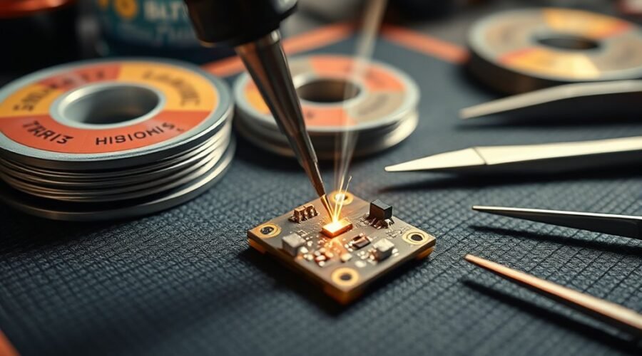
Learning how to solder electronics starts with a temperature-controlled iron, the right solder and flux, a safe workstation, and a repeatable technique. Beginners should practice on an inexpensive through-hole board before repairing valuable electronics. Good soldering is mainly about transferring enough heat to the joint, getting complete wetting, and removing the heat before the board or component is damaged.
Quick Answer
For beginner electronics soldering, use a temperature-controlled iron, small or medium chisel tip, electronics-grade solder, suitable flux, a secure stand, eye protection, and fume extraction. Start near 330–350°C when no manufacturer setting is available, heat the pad and lead together, feed solder into the joint, and inspect for complete wetting without bridges.
Key Takeaways
- A beginner soldering kit should include a temperature-controlled iron, safe stand, electronics-grade solder, tip cleaner, cutters, solder wick, eye protection, and practice parts.
- Sn63Pb37 solder melts at 183°C, Sn60Pb40 across about 183–190°C, and common SAC lead-free alloys around 217–220°C; these melting points are not the same as the iron-tip setting.
- Use source capture or a suitable fume extractor for flux fumes, keep food and drinks away, and wash your hands after soldering, especially when leaded solder is used.
- Heat the component lead and PCB pad together, feed solder to the heated joint rather than carrying a blob on the tip, then remove the solder wire before the iron.
- Inspect for complete wetting, bridges, cracks, excess solder, and disturbed joints before applying power.
At a Glance
| Time Required | About 10–30 minutes to practice several basic through-hole joints |
| Difficulty | Beginner |
| Tools Needed | Temperature-controlled iron, stand, solder, tip cleaner, cutters, solder wick, PCB holder or vise, eye protection, and fume extraction |
| Cost | Varies by station and accessories; the iron or soldering station is normally the largest reusable expense |
Warning: Disconnect power and remove batteries before soldering or desoldering. Keep the hot iron in its stand, wear eye protection, capture flux fumes away from your breathing zone, and keep food and drinks away from the workbench. Wash your hands thoroughly after handling solder and flux.
Pick a Beginner Soldering Kit
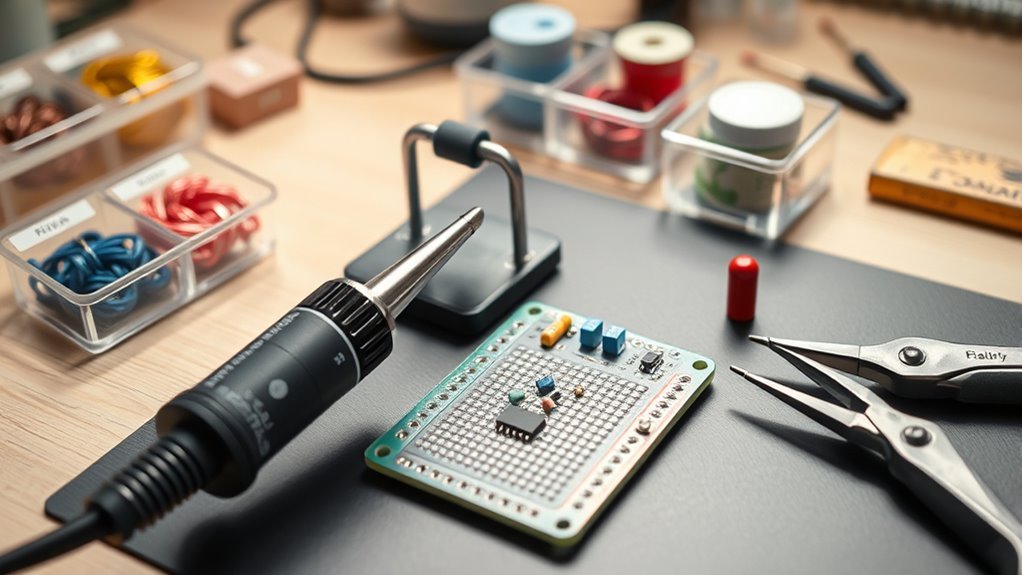
A beginner soldering kit should provide the core tools needed to work safely and repeatably: a temperature-controlled soldering iron, stable stand, solder, tip-cleaning supplies, cutters, solder wick, and a way to hold the circuit board.
A variable-temperature iron is much easier to learn with than a basic uncontrolled iron. A station in roughly the 40–70 watt class is common for hobby electronics, but wattage does not tell you the operating temperature. Higher available power mainly helps the iron recover heat when a large pad, wire, connector, or ground plane pulls heat out of the tip.
Temperature control determines the setpoint; available heater power and tip design determine how well the iron maintains that temperature when it touches the joint.
Some kits include a small practice board or through-hole components. These are useful because you can learn heat control, component placement, solder flow, and desoldering without risking an expensive device.
Suppliers such as SparkFun and Adafruit publish beginner-oriented soldering material, but the most important buying criteria are stable temperature control, an insulated stand, readily available replacement tips, and suitable electrical certification for your region.
Choose a Useful Tip Shape
For most beginner through-hole work, a small or medium chisel tip is easier to use than an extremely fine needle tip. The flat surface transfers heat efficiently to both the PCB pad and component lead. Use a tip that fits the joint without touching nearby pads or plastic parts.
Very small tips can struggle on large copper areas because they have little thermal mass and contact area. Moving to a slightly larger tip is often better than simply increasing the temperature.
Choose Solder and Flux
Solder alloy controls melting behavior, while flux removes surface oxides and helps molten solder wet clean metal. The solder’s melting point is much lower than the temperature normally displayed on the soldering station because the tip must transfer heat into the joint.
According to Kester’s solder-alloy temperature data, Sn63Pb37 melts at 183°C, Sn60Pb40 melts across about 183–190°C, and many common tin-silver-copper lead-free alloys melt around 217–220°C.
Sn63Pb37 melts at 183°C, Sn60Pb40 across 183–190°C, and common SAC lead-free alloys around 217–220°C. The iron-tip setpoint must be higher because the joint continuously absorbs heat.
Solder Alloy Selection
63/37 tin-lead solder is eutectic, so it changes from liquid to solid at a single temperature without a broad plastic phase. 60/40 tin-lead solder has a narrow melting range and is also forgiving for hand work.
Lead-free alloys such as SAC formulations melt at higher temperatures and usually need somewhat more heat at the joint. They avoid intentionally added lead, but they do not eliminate flux fumes, hot-tool hazards, or the need for good hygiene.
For general through-hole electronics, solder wire around 0.5–0.8 mm is easy to control. Delicate pads and fine-pitch work often benefit from thinner wire because it is easier to meter a small quantity.
The European Union’s RoHS rules restrict lead and other hazardous substances in covered electrical and electronic equipment, subject to defined scope and exemptions. Other jurisdictions and applications have different requirements, so alloy choice should follow the product’s technical and regulatory requirements.
Flux Type Choices
Flux selection affects oxide removal, wetting, residue, and cleanup. Electronics solder wire commonly contains flux in its core, but extra flux can help during rework or on oxidized surfaces.
No-clean flux may leave a small amount of residue that is designed to remain on the assembly under the manufacturer’s stated conditions. “No-clean” does not literally mean that nothing remains.
Rosin or mildly activated flux is common in electronics and can provide good wetting. Whether residue should be removed depends on the specific chemistry, cleanliness requirements, and manufacturer instructions.
Water-soluble organic-acid flux is more active and normally requires thorough post-solder cleaning. Residue left behind can attract moisture or become corrosive, so follow the flux manufacturer’s process instructions.
Set Up a Safe Soldering Bench
A safe soldering bench should be stable, well lit, uncluttered, and covered with a heat-resistant or noncombustible work surface. The iron stand should be placed where the hot tool cannot be knocked onto cables, paper, plastic packaging, or clothing.
Keep the board holder, solder, cutters, flux, cleaner, and wick within easy reach so you do not have to reach across the hot iron.
Essential Bench Tools
A compact beginner bench can handle most through-hole practice and simple repair work without specialized industrial equipment.
| Tool | Function |
|---|---|
| Temperature-controlled iron | Supplies controlled heat to the joint |
| Iron stand | Keeps the hot iron secured when not in use |
| Brass tip cleaner or damp cellulose sponge | Removes excess solder and surface contamination from the tip |
| Flux | Improves wetting by helping remove oxides |
| Solder wick | Removes excess solder and bridges |
| Flush cutters | Trim through-hole leads after soldering |
| PCB vise or helping hands | Keeps the work from moving while solder solidifies |
| Fume extraction | Captures soldering smoke away from the breathing zone |
| Safety glasses | Protect against solder or clipped-lead splatter |
Ventilation and Safety
Flux smoke should not be allowed to rise directly into your face. The NIOSH Pocket Guide identifies rosin-core solder pyrolysis products as an inhalation hazard that can irritate the eyes, nose, throat, and respiratory system.
Use local exhaust or a suitable benchtop fume extractor positioned to pull smoke away from your breathing zone. A fan that only blows smoke around the room is less effective than capturing it close to the joint.
When using leaded solder, contamination control is also important. UC San Diego’s lead-soldering safety guidance recommends keeping food and drinks out of soldering areas and washing hands when the work is finished.
Wear safety glasses when soldering and when trimming leads. Return the iron to its stand whenever it leaves the joint, and turn the station off when the work is complete.
Prepare the Board and Components
Before applying heat, make sure the circuit is fully de-energized. Remove batteries and external power. For repair work, follow the device’s service procedure for any components that can retain hazardous charge.
Inspect the pad and lead for oxidation, dirt, oil, or old burnt flux. Clean suitable PCB surfaces with an electronics-safe method recommended for the assembly. Solder will not wet reliably onto heavily oxidized or contaminated metal.
Check Component Polarity and Orientation
Place every component correctly before soldering. Resistors are generally non-polarized, but LEDs, diodes, electrolytic capacitors, many connectors, transistors, and integrated circuits have a required orientation.
Confirm the PCB markings, component datasheet, or assembly drawing before making the joint. Fixing a reversed part after every lead has been soldered is much harder than checking it first.
Protect ESD-Sensitive Parts
Some integrated circuits, MOSFETs, sensors, and other semiconductor devices can be damaged by electrostatic discharge. The EOS/ESD Association describes grounded personnel, wrist straps, and static-dissipative work surfaces as common controls for ESD-sensitive assemblies.
For ESD-sensitive work, use an appropriate grounded ESD mat and wrist strap with compatible equipment. Keep the circuit de-energized while soldering and follow the component manufacturer’s handling instructions.
Tin Your Soldering Iron Tip
To tin a soldering iron tip, melt a small amount of solder over the working surface so the plated area remains wetted. A properly tinned tip transfers heat more effectively and resists oxidation.
Clean the hot tip with a purpose-built brass-wire cleaner or a damp cellulose sponge, then apply fresh solder. Avoid ordinary files, sandpaper, or aggressive abrasives because they can damage the plated surface.
HAKKO’s tip-maintenance guidance recommends keeping the working area coated with solder, using the lowest practical soldering temperature, and leaving solder on the tip when it rests in the holder.
Proper tinning leaves the working surface evenly wetted with solder, improving heat transfer while helping protect the plated tip from oxidation.
Pro Tip: Clean the tip immediately before making the next joint, not before leaving the iron idle. Then add fresh solder before returning the iron to its stand at the end of a work session.
If solder refuses to wet the tip, first check for oxidation, contamination, inadequate temperature, or a worn-out plated surface. Use manufacturer-approved tip tinner or restoration products for stubborn oxidation rather than grinding the tip.
Choose the Right Soldering Temperature
There is no single correct soldering-iron temperature for every electronic joint. Alloy, tip size, copper area, connector mass, station power, and component heat sensitivity all influence the required setpoint.
When no manufacturer or process specification is available, HAKKO suggests beginning around 330–350°C and adjusting from there. For ordinary hobby work, a practical starting point is often around 320–350°C for tin-lead solder and roughly 350–380°C for common lead-free work, but these are starting ranges rather than universal requirements.
| Solder | Approx. Melting Behavior | Reasonable Starting Tip Range |
|---|---|---|
| Sn63Pb37 | 183°C | About 320–350°C |
| Sn60Pb40 | 183–190°C | About 320–350°C |
| Common SAC lead-free | About 217–220°C | About 350–380°C |
Note: If a joint only works after pushing the temperature unusually high, check the tip size, tip condition, station recovery, pad size, and cleanliness first. A larger clean tip often transfers heat better than a tiny tip set excessively hot.
Heat the Joint, Then Feed Solder
The basic sequence is simple: place the tinned tip against both the component lead and PCB pad, allow them to heat, feed solder into the heated joint, remove the solder wire, then remove the iron.
Do not routinely melt a large blob onto the iron and carry it to the joint. That approach can consume the flux before it reaches the surfaces that need cleaning and wetting.
Heat Both Surfaces
Touch the useful side of the soldering tip to both the pad and component lead at the same time. Hold it only long enough for the surfaces to reach a temperature where solder begins to wet them.
A fixed “three- or four-second” rule is not reliable. A small pad may heat almost immediately, while a large ground connection can take longer. Use the shortest dwell that produces good wetting without damaging the board or component.
If a joint repeatedly needs excessive time, stop and check the tip size, tip oxidation, temperature, and surface cleanliness rather than continuing to cook the PCB.
Feed Solder Into Joint
With the iron still touching the pad and lead, bring solder wire to the heated joint from the opposite side or nearby. It should melt and flow across the metal surfaces rather than form a separate ball.
Feed only enough solder to wet the pad and lead and form a controlled fillet. Remove the solder wire first, then lift away the iron. Keep the component still while the solder solidifies.
A good joint normally shows smooth, complete wetting between the lead and pad without cracks, gaps, or an oversized blob.
Note: Tin-lead solder often solidifies with a bright surface. Lead-free joints may appear more matte, so shine alone should not be used to decide whether a joint is acceptable.
Solder Through-Hole Parts
Through-hole soldering secures component leads that pass through plated holes in a PCB. The method is ideal for beginners because the parts are large enough to handle and the completed joints are easy to inspect.
- Disconnect all power and confirm component orientation.
- Insert the component leads through the correct holes.
- Secure the component so it cannot move when the board is turned over.
- Clean and tin the soldering tip.
- Touch the tip to the pad and lead together.
- Feed a small amount of solder into the heated joint.
- Remove the solder wire first, then the iron.
- Let the joint cool without movement.
- Inspect the fillet for wetting, cracks, excess solder, or bridges.
- After the joint is cool, trim the protruding lead while controlling the clipped piece so it cannot fly toward your eyes or nearby circuitry.
The objective is a clean, controlled fillet that wets both surfaces. More solder does not automatically make a stronger or more reliable connection.
Fix Mistakes With Solder Wick
Solder wick, also called desoldering braid, is woven copper braid that removes molten solder through wetting and capillary action. It is useful for excess solder, bridges, and clearing a pad during rework.
Place fresh braid over the unwanted solder, then place the iron on the braid. When the solder melts, it is drawn into the copper strands. Lift the iron and braid carefully rather than dragging the braid across delicate pads.
Choose a braid width close to the area being worked on. Narrow braid gives better control on small pads; wider braid removes more solder from larger joints.
Once a section of braid has filled with solder, cut it off and continue with a fresh section. Do not keep heating a saturated piece because it will no longer absorb solder effectively.
Spot Cold Joints and Bridging
A cold or poorly wetted joint occurs when solder fails to bond correctly to the lead, pad, or both. Causes include insufficient heat, oxidation, dirty surfaces, exhausted flux, or movement while the solder is solidifying.
A solder bridge occurs when solder unintentionally connects adjacent pads or leads. Bridges can create short circuits and should be corrected before power is applied.
| Problem | Likely Cause | Fix |
|---|---|---|
| Solder balls up instead of spreading | Oxidized or contaminated surface, poor flux action, or inadequate heating | Clean the surfaces, add appropriate flux, and heat pad and lead together |
| Cold or disturbed joint | Insufficient heat or movement during cooling | Reflow with fresh flux if needed and hold the part still while it solidifies |
| Solder bridge | Too much solder or poor placement | Remove excess with fresh solder wick and inspect adjacent pins |
| Tip will not accept solder | Oxidized or damaged tip | Clean using approved methods, re-tin, or replace the tip if the plating is damaged |
| Lifted PCB pad | Too much heat, excessive dwell, or mechanical force during rework | Stop heating and assess the trace/pad damage before continuing |
| Joint requires unusually long heating | Tip too small, poor thermal recovery, dirty tip, or large copper plane | Use a suitable larger tip and verify tip condition before raising temperature |
Choose Leaded or Lead-Free Solder
The choice between leaded and lead-free solder depends on the product, regulations, service requirements, and workshop safety policy.
Sn63Pb37 and Sn60Pb40 are easy to hand-solder because of their relatively low melting temperatures and good wetting characteristics. If leaded solder is used, prevent hand-to-mouth contamination: keep it away from food areas and wash your hands thoroughly after working.
Common SAC lead-free solder melts at a higher temperature and may require greater thermal input, especially on large pads. Its finished surface can also appear more matte than traditional tin-lead solder.
Lead-free solder eliminates intentionally added lead from the alloy but should not be treated as hazard-free. Flux smoke, molten solder, cleaners, hot tools, and other alloy constituents still require appropriate controls.
Commercial electronics frequently use lead-free processes partly because regulations such as EU RoHS restrict lead in covered electrical and electronic equipment. Exemptions and regional differences exist, so repairs for regulated products should follow the manufacturer’s approved material and process.
Inspect and Test Before Powering Up
After every joint has cooled, inspect the board under good lighting. Look for solder bridges, incomplete wetting, loose leads, cracked joints, clipped-wire debris, damaged insulation, and components installed in the wrong orientation.
With the circuit still unpowered, a multimeter can help check continuity where a connection is supposed to exist and detect obvious shorts between rails or neighboring conductors where no connection should exist. Interpret meter readings according to the actual circuit rather than assuming every low-resistance reading is a fault.
Remove loose solder fragments and clipped leads before reconnecting power. For a newly assembled project, follow the kit or circuit manufacturer’s recommended first-power procedure.
Practice Simple Joints First
Beginners should start with simple through-hole joints before attempting fine-pitch surface-mount work or valuable repairs. Practice boards let you learn solder quantity, tip position, heat transfer, and inspection without creating an expensive failure.
- Clean and tin the tip before the joint.
- Secure the board and component.
- Heat the pad and lead together.
- Feed solder into the heated joint.
- Remove the solder, then the iron.
- Do not move the joint while it solidifies.
- Inspect wetting, shape, and clearance from nearby conductors.
Focus on consistency rather than speed. Once you can repeatedly produce small, fully wetted joints without bridges or overheating, move on to denser boards, wires, connectors, and basic repair work.
Frequently Asked Questions
How do I clean oxidation from a soldering iron tip?
Clean the hot tip with a purpose-built brass-wire cleaner or damp cellulose sponge, then immediately re-tin it with fresh solder. For stubborn oxidation, use a manufacturer-approved tip-tinning or restoration compound. Avoid files, sandpaper, and aggressive abrasives because they can damage the plated surface.
What temperature should I use for different solder types?
Follow the solder, component, or process manufacturer’s specification when one exists. Otherwise, a useful starting point is around 330–350°C, then adjust only as needed. Tin-lead work often falls around 320–350°C and common lead-free work around 350–380°C, depending on tip size, joint mass, and station recovery.
How can I tell if my flux is expired?
Do not judge flux only by color or thickness. Check the manufacturer’s shelf-life information, lot date, storage requirements, technical data sheet, and safety data sheet. If the flux has separated abnormally, dried out, been stored outside its specified range, or no longer wets properly on a clean test piece, replace it rather than risking the assembly.
Which solder diameter works best for delicate electronics?
Fine solder around 0.3–0.6 mm is convenient for small pads because it lets you feed very small amounts. General through-hole work is also comfortable with wire around 0.5–0.8 mm. Diameter affects dosing, not the alloy’s electrical quality, so choose a size that matches the pad and lead.
How do I safely dispose of used solder and flux waste?
Keep solder scraps, spent braid, contaminated wipes, and chemical flux or cleaner waste separate from ordinary workbench debris. Lead-containing waste may require hazardous-waste handling depending on local rules. Do not pour flux or cleaning chemicals into a drain unless the manufacturer and local regulations specifically permit it. For household quantities, contact your local waste or hazardous-waste program; the U.S. EPA recycling guidance also recommends checking local collection requirements.
Why will solder not stick to my soldering iron tip?
The tip is commonly oxidized, contaminated, too cool, or physically worn. Clean it with the recommended sponge or wire cleaner, apply fresh solder, and use approved tip-restoration compound if needed. If the plated working surface is damaged and still will not wet after proper cleaning, replace the tip.
Do I need extra flux if my solder already has a flux core?
Not always. Fresh, clean through-hole joints often solder well with flux-cored wire alone. Extra compatible flux is useful during rework, desoldering, or when surfaces are mildly oxidized. Use a flux intended for electronics and follow its residue-cleaning requirements.
Conclusion
Soldering electronics becomes much easier once heat transfer, surface cleanliness, flux, and solder quantity are treated as parts of the same process. Start with a temperature-controlled iron, a useful tip size, a secure and ventilated workstation, and inexpensive practice boards. Tin the tip, heat both surfaces, feed solder to the joint, let it cool without movement, and inspect every connection before applying power.
Use the lowest practical temperature that produces prompt wetting, increase tip size before resorting to excessive heat, and treat fume extraction, eye protection, handwashing, and power isolation as normal parts of the job. These habits improve joint quality while reducing damaged pads, oxidized tips, solder bridges, and unnecessary rework.
Sources
- Kester — Alloy Temperature Chart — melting temperatures and ranges for tin-lead and lead-free solder alloys.
- HAKKO — Soldering Tip Maintenance Guidance — temperature selection, tip cleaning, tinning, and oxidation prevention.
- CDC/NIOSH — Rosin Core Solder Pyrolysis Products — solder-flux fume exposure routes and respiratory effects.
- UC San Diego Environmental Health & Safety — Lead Soldering Safety — lead hygiene, ventilation, eye protection, and workspace controls.
- European Commission — RoHS Directive — current restrictions on hazardous substances including lead in covered electrical and electronic equipment.
- EOS/ESD Association — Basic ESD Control Procedures — grounding, wrist straps, and static-dissipative workstations for ESD-sensitive electronics.