Projection weld symbols tell fabrication and inspection personnel how localized resistance welds are to be shown on a drawing. The most important point is that a projection weld does not have a unique basic circle of its own: under AWS A2.4:2020, it uses the same circular weld symbol as a spot weld, with the projection-welding process identified in the tail. Correctly reading the symbol, dimensions, and reference-line position prevents costly mistakes.
Quick Answer
Under AWS A2.4:2020, a projection weld uses the same circular weld symbol as a spot weld. Projection welding is identified by the process reference in the tail, normally PW. Weld size is shown to the left, pitch to the right, and quantity in parentheses, while symbol position can identify the member carrying the projection.
Key Takeaways
Key Takeaways
- A projection weld uses the same basic circular weld symbol as a spot weld; the projection-welding process must also be identified, commonly as PW in the tail.
- Do not confuse the circular spot/projection weld symbol with the weld-all-around circle at the junction of the arrow and reference line.
- For projection welding, symbol position relative to the reference line can identify which joint member carries the projection or embossment.
- A size shown to the left refers to the required weld size or weld diameter, not automatically to the physical diameter of the formed projection.
- Pitch is the center-to-center spacing between welds and appears to the right; a required number of welds is shown in parentheses.
- Use AWS A2.4:2020 together with the drawing, applicable welding specification, procedure, and project requirements rather than treating the symbol alone as a complete welding procedure.
What Are Projection Weld Symbols?
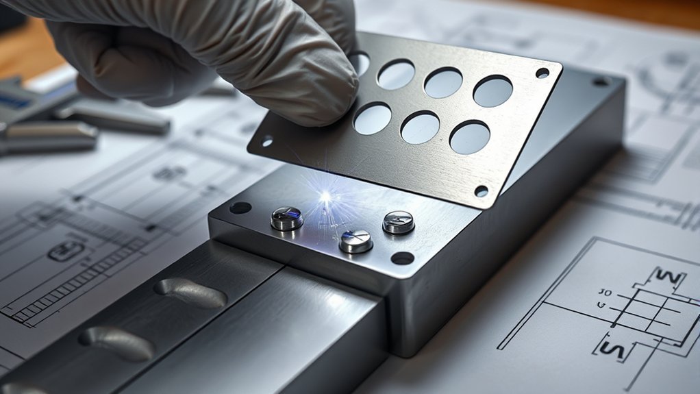
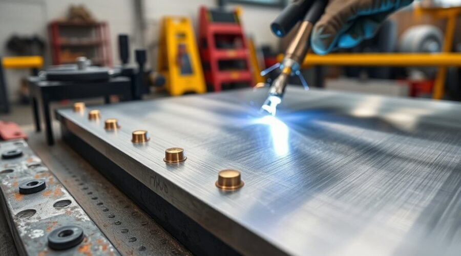
Projection welding is a resistance-welding process in which current and force create welds at predetermined contact points formed by projections, embossments, or intersections. The American Welding Society describes the process as localizing weld formation at those defined points.
On an AWS welding symbol, projection welding uses the same basic circular weld symbol used for spot welding. The drawing therefore needs additional process information to make clear that projection welding, rather than another spot-welding process, is required. Under AWS process designations, PW means projection welding.
The reference line provides the framework for the symbol. Depending on the application, the circle may be shown above, below, or in the appropriate position on the reference line. For a projection weld with member significance, that placement helps identify the joint member that carries the projection or embossment.
The formed projection concentrates electrical resistance and heating at a selected location. During the weld cycle, electrode force and current cause the projection to heat and collapse as the weld develops. Actual weld quality still depends on material, projection geometry, electrode force, current, weld time, tooling, fit-up, and the qualified or specified welding procedure.
Projection welding is a resistance-welding process and should not be confused with the arc-welding equipment covered in guides such as welders for beginners, multi-process welders, or conventional MIG, TIG, and stick machines.
Projection Weld Symbol vs Weld-All-Around Symbol
Warning: A circle located at the junction where the arrow meets the reference line is the AWS weld-all-around supplementary symbol. That is not the projection-weld symbol. The spot/projection weld circle is a basic weld symbol associated with the reference line itself.
This distinction is essential because both markings involve circles but communicate completely different requirements. A weld-all-around symbol tells the welder about the extent of welding around a joint. A spot/projection circle identifies a localized weld type and must be interpreted with its dimensions and process information.
| Feature | Meaning | Where to Look |
|---|---|---|
| Circle used for spot/projection welding | Basic weld symbol for a localized spot-type weld | At the reference line in the weld-symbol position |
| PW in the tail | Projection welding process designation | Tail of the welding symbol |
| Circle at arrow/reference-line junction | Weld-all-around supplementary symbol | At the junction of the arrow and reference line |
How to Read a Projection Weld Symbol
Read a projection weld symbol in a consistent order. First identify the circular spot/projection weld symbol. Next verify that the drawing identifies projection welding, normally through the PW process reference in the tail. Then read symbol position, weld size or strength, quantity, pitch, drawing extent, and any additional notes.
- Identify the circle correctly. Confirm that it is the basic spot/projection weld symbol rather than the weld-all-around circle at the arrow junction.
- Check the tail. Look for PW or another clear reference establishing that projection welding is the required process.
- Determine member significance. Use the circle’s position relative to the reference line together with the arrow to determine which joint member carries the projection when side significance applies.
- Read the value to the left. When size is specified there, read it as the required weld size or weld diameter.
- Read the quantity. A definite number of welds may be placed in parentheses in accordance with the symbol convention.
- Read the pitch to the right. Pitch is center-to-center spacing between welds in a straight line.
- Check the drawing for extent and projection geometry. Do not assume that every required physical dimension of the projection itself is encoded beside the weld circle.
| Element | Read As | What It Controls |
|---|---|---|
| Circle | Spot/projection basic weld symbol | Weld-symbol family |
| PW in tail | Projection welding | Process identification |
| Left-side size | Weld size / weld diameter | Required size of each weld |
| Number in parentheses | Quantity | Required number of welds |
| Right-side value | Pitch | Center-to-center spacing |
| Position above/below line | Member significance | Identifies the relevant arrow-side or other-side member |
| Tail | Process/specification/reference | Distinguishes projection welding and carries additional requirements |
Pro Tip: Do not begin by interpreting the number beside a circle. First determine exactly which circle you are looking at and whether the tail identifies PW. That one check prevents several common projection-weld-symbol mistakes.
Arc-welding machine specifications such as the Hobart Handler 140 vs Lincoln 140 comparison describe different welding processes and should not be used to interpret a PW resistance-welding symbol.
Spot the Arrow Side and Other Side
For spot, projection, plug, slot, and seam symbols, the arrow establishes an arrow-side member. AWS describes the member toward which the arrow points as the arrow-side member; the opposing joint member is the other-side member.
For projection welding, this distinction matters because the projection or embossment belongs to a particular member. A symbol placed below the reference line follows the arrow-side convention, while one placed above follows the other-side convention. The purpose is to communicate which member carries the projection when member significance applies.
This is more precise than saying the arrow simply shows “where the weld is applied.” The weld forms at the interface between the members. The drawing convention helps identify the member associated with the projection geometry.
Note: The arrow-side/other-side convention must be interpreted using the drawing’s specified symbol standard. Do not automatically transfer AWS conventions to a drawing prepared under another standard system.
Decode Size, Pitch, and Quantity
A projection weld symbol can carry several dimensions, but each has a specific meaning. The most important correction is that the value to the left is not automatically the diameter of the physical projection stamped into the part.
Weld Size
When size is used, the value to the left specifies the required weld diameter. This is the weld formed at the faying surfaces, not necessarily the original diameter, width, or height of an embossment or machined projection.
Strength
AWS A2.4:2020 also allows a spot-type weld requirement to be specified by strength rather than only by weld diameter. The current convention places a strength requirement as a note in the tail. The applicable design or resistance-welding specification determines what strength or acceptance requirement is appropriate.
Quantity
When a definite number of welds is required, the number is shown in parentheses according to the AWS spot-weld notation convention. For example, (4) indicates four required localized welds when used in the proper symbol arrangement.
Pitch
Pitch is the center-to-center distance between adjacent welds in a straight line. It is shown to the right of the circular weld symbol.
Extent
Do not invent a “projection weld length” from the right-side number. If the weld pattern covers only part of a joint or a specific region, the required extent is dimensioned or otherwise identified on the drawing.
For projection welding, keep three different ideas separate: the geometry of the formed projection, the size or strength of the resulting weld, and the spacing or pattern of multiple welds.
Likewise, an article about stick welders concerns a different process. Stick-welding amperage, electrode selection, and bead dimensions do not change the AWS meaning of a projection-weld symbol.
Worked Projection Weld Symbol Example
Suppose a drawing shows a circular spot/projection symbol, identifies PW in the tail, gives a weld-size value to the left, shows (4) for quantity, and provides a pitch value to the right.
Read it in this order:
- The circle establishes the spot/projection weld-symbol family.
- PW confirms that the required process is projection welding.
- The circle’s position relative to the reference line identifies the applicable member when the projection-bearing member has side significance.
- The left-side value gives the required weld diameter.
- (4) requires four welds.
- The right-side pitch gives the center-to-center spacing between the four weld locations.
- Any embossment height, projection profile, row location, pattern extent, tolerances, or additional acceptance requirements are taken from the drawing, specification, or referenced procedure rather than guessed from the circle.
This sequence is safer than trying to memorize every number by position without first confirming the process and member orientation.
Use Projection Weld Symbols on Drawings
On an engineering drawing, projection-weld notation should communicate fabrication intent without forcing production personnel to guess the designer’s requirements. The symbol identifies the weld requirement, while the drawing or referenced specifications can provide projection geometry, component dimensions, tolerances, location, inspection requirements, and process details.
Before releasing or fabricating from a drawing, verify:
- The arrow clearly identifies the intended joint or member.
- The circular symbol is not being confused with the weld-all-around supplementary symbol.
- Projection welding is identified through PW or an equivalent explicit process reference permitted by the drawing standard.
- The required weld size or strength is unambiguous.
- Quantity and pitch agree with the intended pattern.
- The physical projection or embossment geometry is defined where necessary.
- The extent and location of the weld pattern are dimensioned clearly.
- Applicable welding procedures, specifications, acceptance criteria, and inspection requirements are referenced separately where needed.
Good workholding is also important in production, but a fabrication surface or fixture such as those discussed in a welding table guide does not replace the drawing requirements or a resistance-welding fixture designed for the specific projection-weld application.
Projection, Spot, and Seam Welds Compared
Projection, spot, and seam welding are all commonly associated with resistance-welding applications, but the processes form welds differently and should not be identified from an oversimplified sketch.
| Process | How Weld Location Is Established | Drawing/Symbol Point |
|---|---|---|
| Projection welding | Current and force are concentrated at projections, embossments, intersections, or other defined contact features. | Uses the spot-type circular weld symbol; projection welding must be identified by the process reference, such as PW. |
| Resistance spot welding | Electrodes concentrate current and force at discrete spots without requiring the same formed projection feature. | Uses the circular spot weld symbol with the appropriate resistance-spot-welding process reference where required. |
| Resistance seam welding | A succession of welds forms a seam, commonly with rotating wheel electrodes. | Uses the AWS seam-weld symbol and its own rules for size, length, pitch, quantity, and orientation. |
Projection Weld Basics
Projection welding is a resistance welding process. Electrical resistance generates heat at selected contact locations while electrode force acts on the workpieces. Raised projections, embossed features, annular projections, cross-wire intersections, or similar geometry concentrate the process at predetermined points.
The process can be useful for applications such as attaching weld nuts or other components and for cross-wire assemblies. Multiple projections may also allow more than one weld to be produced during a cycle when the machine, tooling, component geometry, and welding schedule are designed for it.
The basic AWS projection-weld symbol is not a triangle. It uses the same circular weld symbol as a spot weld and relies on the process reference to establish projection welding.
Projection welding also does not use conventional TIG equipment. A TIG welder comparison therefore concerns a separate arc-welding process rather than the PW resistance-welding method discussed here.
Spot And Seam Differences
Spot welding creates individual localized resistance welds. Projection welding also creates localized welds, but it uses intentional projections, embossments, intersections, or related contact features to concentrate current and force at predetermined locations.
Seam welding differs because the objective is a welded seam rather than isolated projection welds. Its AWS weld symbol is distinct from the plain spot/projection circle, and its dimensional rules should be read from the seam-welding provisions rather than copied into projection-weld notation.
That means a reader should never decide that a circle represents projection welding solely from shape. Process information and the surrounding drawing context are essential.
Common Projection Weld Symbol Mistakes
Misreading Size Notation
A common error is to assume that a number to the left of the circular symbol describes the diameter of the stamped projection. Under the AWS spot/projection convention, a size value there specifies the required weld diameter.
For example, if the drawing specifies a weld diameter at that location, fabricators should not automatically machine or emboss the projection to that same physical diameter. Projection height, width, included angle, annular shape, or other geometry may be controlled elsewhere on the detail drawing or by a referenced specification.
Confusing Pitch And Length
For a straight line of spot-type welds, pitch means center-to-center spacing and is shown to the right of the circular weld symbol. The original idea that projection-weld “length” must appear first and pitch after a hyphen is not the AWS spot/projection rule.
Where only a defined portion of a joint is to receive the weld pattern, the drawing should establish that extent with dimensions or other clear drawing information.
Ignoring Arrow Side Rules
The arrow and the circle’s position relative to the reference line are important because projection welding may need to identify which member carries the projection or embossment.
- Identify which member the arrow points toward.
- Determine whether the circle is below, above, or otherwise positioned according to the specified AWS convention.
- Confirm that PW or another explicit process reference establishes projection welding.
- Read size, quantity, pitch, and additional notes only after the member orientation is clear.
Do not substitute an unrelated consumable-selection rule for symbol interpretation. For example, information about general-purpose welding rods applies to processes such as shielded metal arc welding, not to decoding a projection-welding symbol.
Confusing the Circle at the Arrow Junction
This is one of the highest-risk mistakes. The small circle at the junction of the arrow and reference line is the weld-all-around symbol. A projection-weld requirement uses the spot/projection weld circle in the weld-symbol location and requires projection-welding process identification.
If a drawing seems to show both, interpret each element independently rather than treating every circle as a projection weld.
Assuming the Symbol Defines the Whole Process
AWS A2.4 standardizes how welding information is communicated; it does not by itself establish every design requirement, welding schedule, tolerance, or acceptance criterion. Those requirements may come from a drawing note, WPS, company specification, product standard, code, or project specification.
Warning: Never use a symbol-reading article as a substitute for the applicable drawing, WPS, resistance-welding specification, equipment instructions, employer safety program, or code requirements. Incorrect resistance-welding setup can damage parts or equipment and can expose personnel to electrical, mechanical, burn, and fume hazards.
Projection Weld Symbol Standards to Know
For AWS-style drawings, the main symbol reference is AWS A2.4:2020, Standard Symbols for Welding, Brazing, and Nondestructive Examination. As of September 2026, AWS continues to list the 2020 edition as its current A2.4 standard.
AWS A2.4:2020 provides the system used to communicate weld location and related information on drawings. Its projection-welding provisions identify the projection weld symbol as the same basic symbol used for spot welding and require the projection-welding process to be referenced in the tail. AWS’s process table uses PW for projection welding.
The welding process itself is described by AWS in Introduction to Projection Welding, which explains that projection welding is a resistance-welding process that localizes welds at predetermined projections, embossments, or intersections.
For resistance-weld performance requirements, symbol interpretation may also need to be used alongside a material or product specification. For example, AWS lists AWS C1.4M/C1.4:2025 for resistance welding of carbon and low-alloy steels. That type of specification addresses requirements beyond simply drawing the welding symbol.
Existing internal information about welding processes can provide broader context, but AWS standards and the controlling project documents should be used for formal symbol interpretation.
AWS vs Other Welding-Symbol Standards
Do not assume every fabrication drawing uses AWS A2.4. International projects may use other symbol systems, including ISO-based conventions. AWS A2.4:2020 itself includes comparative information concerning ISO welding symbols.
Before interpreting a production drawing, check the title block, general notes, customer specification, or drafting standard to determine which symbol system governs. Mixing rules from different systems can change how reference-line placement, dimensions, and supplementary information are interpreted.
Frequently Asked Questions
How Do You Interpret Weld Symbols?
Start with the reference line and arrow, identify the basic weld symbol, determine whether it is above, below, or centered relative to the line, and then read dimensions and supplementary information in their standard locations. Finally, check the tail for the welding process, specification, or other reference. Always use the symbol standard specified by the drawing.
Is a Projection Weld Symbol the Same as a Spot Weld Symbol?
The basic AWS circular weld symbol is the same. What establishes projection welding is the projection-welding process reference in the tail, normally PW, together with the symbol position and drawing details. A plain circle by itself should not automatically be interpreted as projection welding.
What Does PW Mean on a Welding Symbol?
PW is the AWS letter designation for projection welding. When the spot-type circular symbol is used for projection welding, the process reference in the tail distinguishes projection welding from other processes that can use the spot weld symbol.
Why Do Welders Drink Milk After Welding?
Drinking milk after welding is a long-standing workplace belief, but milk should not be treated as protection against welding fumes or as a way to neutralize inhaled metals. OSHA emphasizes ventilation, local exhaust, and appropriate respiratory protection where required. NIOSH also warns that welding fumes can contain hazardous metals such as manganese. Milk can be consumed as ordinary food, but it is not a substitute for exposure controls or medical evaluation after significant fume exposure.
How to Show Welding Symbols on Drawings?
Use the reference line and arrow to identify the joint or member, place the required basic weld symbol in its standard location, and add dimensions, supplementary symbols, and tail information only where needed. For a projection weld under AWS A2.4, use the circular spot/projection symbol and identify projection welding in the tail rather than placing a special circle at the arrow junction.
How Do I Read and Interpret Welding Blueprints?
First identify the drawing standard and read the title block, general notes, dimensions, sections, and details. Then interpret the reference line, arrow, weld symbol, dimensions, supplementary marks, and tail as one system. Cross-check the drawing against the applicable WPS, fabrication specification, code, and inspection requirements rather than relying on the weld symbol alone.
Conclusion
Projection weld symbols become much easier to read once the circle is interpreted correctly. Under AWS A2.4:2020, projection welding uses the same basic circular symbol as a spot weld, while the process reference—normally PW—establishes projection welding. Symbol position identifies the relevant member when side significance applies, weld size is read separately from physical projection geometry, quantity is shown in parentheses, and pitch gives center-to-center spacing.
The most important mistake to avoid is confusing that circular weld symbol with the weld-all-around circle at the arrow/reference-line junction. Read the complete welding symbol together with the part drawing, applicable welding procedure, specification, and inspection requirements rather than relying on the circle alone.
Sources
- American Welding Society — AWS A2.4:2020 — current AWS standard for welding, brazing, and nondestructive-examination symbols.
- American Welding Society — Introduction to Projection Welding — projection-welding process fundamentals and localization at projections, embossments, and intersections.
- American Welding Society — AWS C1.4M/C1.4:2025 — resistance-welding requirements for carbon and low-alloy steels.
- OSHA — 29 CFR 1910.252 Welding, Cutting, and Brazing — ventilation, fume-control, and respiratory-protection requirements.
- CDC/NIOSH — Welding Fumes and Manganese — health information on welding-fume exposure.