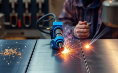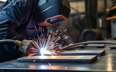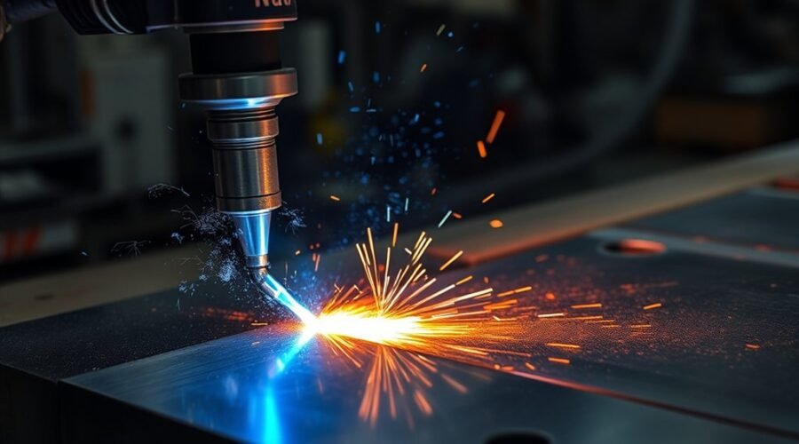
Plasma arc cutting uses a concentrated jet of electrically conductive, ionized gas to melt metal and force the molten material out of the kerf. It works on conductive metals such as mild steel, stainless steel, aluminum, copper, and brass. The quality of the cut depends on the machine, gas, amperage, travel speed, torch height, consumable condition, and material thickness.
Quick Answer
Plasma arc cutting creates an electric arc through a flowing gas, turning that gas into plasma hot enough to melt conductive metal. A high-velocity gas stream then blows the molten metal from the cut. Clean results require the correct gas, amperage, travel speed, torch-to-work distance, and undamaged consumables.
Key Takeaways
- Plasma arc cutting melts electrically conductive metal with a narrow, high-temperature plasma jet and ejects the molten material with gas flow.
- Compressed air is economical and versatile, oxygen is preferred for high-quality mild-steel cutting, and nitrogen or argon-hydrogen is used for selected stainless-steel and aluminum applications.
- Travel speed, amperage, torch height, gas flow, and consumable condition are major causes of dross, bevel, wide kerfs, and incomplete cuts.
- Cutting capacity is machine-specific. Recommended cut capacity, maximum/severance capacity, and pierce capacity are different ratings and should not be treated as interchangeable.
- Plasma is well suited to conductive metals and often offers a useful balance of speed, cut quality, and equipment cost between oxy-fuel and laser processes.
What Is Plasma Arc Cutting?
)
Plasma arc cutting is a thermal metal-cutting process that uses an electric arc and a constricted stream of ionized gas. According to TWI’s explanation of plasma cutting, the jet reaches temperatures above 20,000°C and melts the workpiece while the fast-moving gas ejects molten material from the kerf.
The process requires an electrically conductive workpiece because the transferred cutting arc becomes part of the electrical circuit. Common materials include carbon steel, stainless steel, aluminum, copper, brass, nickel alloys, and other conductive metals.
A plasma cutter does two jobs at once: the arc supplies enough concentrated heat to melt the metal, while the high-speed gas removes that molten metal from the cut.
Plasma systems range from portable handheld units to automated CNC machines. This makes the process useful for repair, fabrication, automotive work, construction, industrial plate cutting, and detailed work such as plasma cutting for hobby and fabrication work.
How Plasma Cutters Work
A plasma cutter sends gas through a small torch opening while electrical energy ionizes that gas. The resulting plasma becomes electrically conductive, transfers the arc to the workpiece, melts a narrow path through the metal, and blows the molten material out of the kerf.
Hypertherm describes plasma-arc temperatures as approaching 40,000°F. The nozzle constricts the arc into a relatively narrow, high-energy stream instead of allowing the heat to spread over a broad area.
- Gas begins flowing through the torch. Depending on the system, this may be compressed air or a dedicated plasma gas.
- The cutter establishes a pilot arc. Starting technology varies. Traditional systems may use high-frequency, high-voltage starting, while many modern handheld units use a contact or blowback starting mechanism.
- The arc transfers to the workpiece. The conductive metal completes the cutting circuit.
- The plasma jet melts the metal. Heat is concentrated around the nozzle opening and cutting arc.
- Gas velocity clears the kerf. Molten material is pushed out through the bottom of the cut.
The gas itself also affects the result. Different plasma gas and air-supply setups can change edge finish, dross, speed, and consumable life.
| Gas | Typical Strength | Common Result |
|---|---|---|
| Compressed air | Economical and versatile | Good general-purpose quality on several metals |
| Oxygen | High productivity on mild steel | Fast cuts with low dross and clean edges |
| Nitrogen | Useful for stainless steel and aluminum | Good edge quality with suitable secondary gas |
Plasma Cutter Parts
A plasma cutting system combines a power source, gas-delivery system, torch, work lead, and replaceable torch components. CNC equipment adds motion control, torch-height control, and other automation, while portable cutters package many functions into a smaller unit.
The power supply provides the DC energy needed for the arc, but there is no single universal 200–400 VDC cutting output. Rated voltage, open-circuit voltage, amperage, and input power vary by machine.
Inside the torch, several parts control the arc and gas:
- Electrode: carries current and provides the starting point for the plasma arc. Electrode construction depends on the torch and plasma gas; air and oxygen systems commonly use a copper electrode with a hafnium-type insert.
- Swirl ring: controls and rotates the gas flow so the arc remains centered and stable.
- Nozzle: shapes and constricts the plasma stream into a narrow jet.
- Shield or retaining components: protect and position other consumables and may help control secondary gas flow.
Electrodes and nozzles gradually erode. A damaged or enlarged nozzle orifice can change arc shape, bevel angle, kerf width, and dross formation. Consumable condition therefore has a direct effect on plasma cutter performance and operating cost.
Which Gases Work Best for Plasma Cutting?
The best plasma gas depends on the metal, thickness, torch, consumables, and desired edge quality. Hypertherm’s plasma-gas selection guidance identifies compressed air, oxygen, nitrogen, and argon-hydrogen among the important choices for common fabrication work.
| Gas | Best-Suited Use | Main Consideration |
|---|---|---|
| Compressed air | General-purpose mild steel, stainless steel, and aluminum cutting | Low gas cost, but the air must be clean and dry |
| Oxygen | Mild steel | Excellent speed and edge quality; not recommended as the plasma gas for stainless steel or aluminum |
| Nitrogen | Stainless steel and aluminum | Good cut quality and consumable life; often paired with a secondary gas |
| Argon-hydrogen | Thicker stainless steel and aluminum on compatible multi-gas systems | High cutting capability but higher cost and specialized equipment requirements |
Compressed air is attractive because it can serve several metals without bottled cutting gas. However, moisture, oil, and particles in shop air can shorten consumable life and reduce cut consistency.
Air plasma can also leave oxidation or nitriding on a cut face. If the edge will be welded, clean and prepare it as required for the material and welding procedure. Gas selection for plasma cutting is separate from choosing a shielding gas for MIG welding.
Plasma Cutting Quality Factors
Good plasma cuts depend on keeping several variables inside the range specified for the torch and material. The most important are travel speed, amperage, torch height, gas flow, torch alignment, and consumable condition. These variables affect dross, bevel angle, kerf width, top-edge rounding, and whether the arc fully penetrates the plate.
Gas Selection Impact
Gas choice affects arc behavior, cutting speed, edge chemistry, dross, and consumable life. It should be selected from the manufacturer’s cut chart rather than treated as an interchangeable shop preference.
- Oxygen: a strong choice for mild steel where clean edges and high cutting speed are priorities.
- Nitrogen: commonly used for stainless steel and aluminum, particularly in multi-gas systems.
- Compressed air: economical and versatile, but contaminated air can reduce torch-part life and edge consistency.
- Argon-hydrogen: used by compatible industrial systems for thicker stainless steel and aluminum applications.
The correct plasma gas is only one part of the setup. Gas pressure or flow must also match the torch, nozzle, current, and cut chart.
Torch Setup Precision
Torch height controls how the plasma jet enters the workpiece. A torch that runs too high, too low, or out of square can produce bevel, dross, poor dimensional accuracy, or accelerated consumable wear.
Standoff is the distance between the torch and workpiece during cutting. Mechanized systems often regulate this distance through arc-voltage-based torch-height control. Hand cutting depends more heavily on operator technique or a drag-cutting setup designed for contact with the workpiece.
Nozzle condition matters as well. An enlarged, nicked, or asymmetrical nozzle opening can deflect the plasma jet. A non-contact pilot arc system can be useful on painted, rusty, expanded, or uneven material when the machine is designed for that operating mode.
Material Thickness Control
Material thickness determines how much energy and time the arc needs to complete the cut. As thickness rises, the machine generally needs more available cutting power and a slower travel speed, but the correct settings should always come from the cutter’s material-specific cut chart.
- Choose consumables and amperage rated for the metal and thickness.
- Set the specified gas or air pressure and confirm adequate flow.
- Use the recommended cut height or drag technique.
- Set travel speed close to the manufacturer’s cut-chart value.
- Inspect the bottom of the cut for full penetration and the type of dross produced.
Trying to compensate for excessive thickness simply by moving very slowly can widen the kerf, increase dross, and overheat consumables. A cutter’s recommended capacity is therefore more useful for routine work than its absolute severance limit.
Why Does a Plasma Cutter Leave Dross?
Dross is re-solidified molten metal that remains attached to the cut. It does not automatically mean the machine lacks power. Hypertherm identifies travel speed, amperage, standoff, consumable condition, material type, and thickness among the variables that affect dross.
- Heavy, bubbly bottom dross: the cutter may be moving too slowly, running too close, or applying excessive energy for the setup.
- A small, hard bead along the bottom: travel may be too fast, torch height may be too great, or available amperage may be too low.
- Top spatter: check nozzle wear, excessive speed, and excessive torch height.
- Dross on only one side or inconsistent bevel: inspect nozzle condition, torch squareness, gas delivery, and machine motion.
Pro Tip: Change one cutting variable at a time. If you alter speed, amperage, pressure, and torch height together, you will not know which adjustment actually improved the cut.
Plasma Cutting Safety: Fumes, Fire, Noise, and Arc Radiation
Plasma cutting creates more than heat. The process can expose the operator to hot metal, sparks, ultraviolet and infrared radiation, electrical hazards, fumes, gases, and high noise. The exact hazards vary with the base metal, coatings, current, cutting environment, and ventilation.
Warning: Do not plasma-cut unknown containers, tanks, coated metal, or material that may contain hazardous substances until the hazards are identified and controlled. Cutting can ignite combustibles and create harmful airborne contaminants.
OSHA’s welding and cutting requirements address fire prevention, combustible materials, confined spaces, and ventilation for hazardous metals and coatings. Local exhaust ventilation is especially important when fumes would otherwise pass through the operator’s breathing zone.
Eye and face protection, flame-resistant clothing, gloves, hearing protection where needed, and suitable ventilation should match the actual cutting process. Never assume ordinary safety glasses alone are enough protection from a visible plasma arc.
Note: Workplace fume exposure and respirator selection depend on the material, coating, process, ventilation, and measured exposure. For occupational work, follow the applicable safety standard and obtain competent industrial-hygiene or safety advice when exposure is uncertain.
Plasma Cutting vs. Oxy-Fuel Cutting
The main difference is the cutting mechanism. Plasma melts conductive metal with an electric arc and ejects it with gas, while oxy-fuel heats suitable steel and uses a stream of oxygen to sustain rapid oxidation. This gives the two processes different strengths.
| Factor | Plasma | Oxy-Fuel |
|---|---|---|
| Material range | Conductive metals including steel, stainless, and aluminum | Best suited to carbon and low-alloy steels that support the oxidation process |
| Thin and medium plate | Usually faster and more precise | Slower and generally creates a larger heat-affected area |
| Very thick carbon steel | Possible with sufficiently powerful industrial systems | A traditional strength of the process |
| Electricity | Required | Not required for a basic torch setup |
| Preheating | No separate preheat step for normal cutting | Metal is heated to ignition temperature before the oxygen cutting stream does its work |
Hypertherm’s industrial cutting-process comparison describes plasma as particularly useful across a broad range of metal thicknesses, while oxy-fuel remains well suited to thick carbon steel.
Portability can favor oxy-fuel where electrical power or compressed air is unavailable. Plasma is often easier to use for mixed-metal fabrication and thinner work. Oxy-fuel equipment such as the Victor Performer and other oxy-acetylene cutting kits can also heat, braze, or weld when configured for those tasks.
Plasma Cutting vs. Laser Cutting
Plasma and laser cutting both use concentrated energy, but they prioritize different production goals. Plasma is widely used for fast, economical cutting of conductive plate, while laser systems are favored when very fine features, narrow kerfs, or tight dimensional control are the main requirements.
| Factor | Plasma Cutting | Laser Cutting |
|---|---|---|
| Energy source | Electrical plasma arc | Focused laser beam |
| Material requirement | Workpiece must be electrically conductive | Not dependent on electrical conductivity in the same way |
| Kerf and detail | Generally wider kerf and less fine-detail capability | Typically better for fine features and narrow kerfs |
| Equipment cost | Typically lower for comparable fabrication applications | Industrial systems usually require higher capital investment |
| Strong use case | Fast plate fabrication across a wide thickness range | Detailed parts and tight tolerances, especially on thinner material |
Laser capability varies greatly with laser type and power, so there is no universal thickness where one process suddenly becomes better than the other. For many shops, the deciding factors are tolerance, feature size, material thickness, production volume, edge-finish requirements, and capital cost.
After cutting, fabrication may continue with processes such as MIG, TIG, or stick welding, depending on the material and joint.
Metals You Can Cut With Plasma
Plasma cutting works on electrically conductive metals. Mild steel, stainless steel, and aluminum are the most common shop materials, but suitable equipment can also cut copper, brass, nickel alloys, titanium, and other conductive metals.
Electrical conductivity is the key requirement because the transferred arc must attach to the workpiece. Wood, ordinary plastics, glass, and similar nonconductive materials are therefore not normal plasma-cutting materials.
The required amperage and practical cutting capacity vary with metal type, thickness, torch design, and process gas. Machine power output also matters when planning a fabrication setup that combines cutting and welding.
Common Plasma-Cut Metals
Different conductive metals respond differently to the plasma jet. Thermal conductivity, alloy chemistry, surface condition, and thickness all affect speed, dross, edge color, and distortion.
- Mild steel: one of the easiest and most common plasma-cut materials. Air is economical, while oxygen plasma is widely used when the system supports it and high cut quality is required.
- Stainless steel: can be cut with air, nitrogen, and other process-specific gas combinations. Edge appearance and weld preparation depend on the chosen process.
- Aluminum: cuts readily with plasma, but its high thermal conductivity makes correct speed and heat input important for controlling dross and distortion.
- Copper and brass: can be plasma cut because they conduct electricity, although their high thermal conductivity can require more capability than similarly sized mild-steel work.
Best Conductive Materials
There is no single “best” plasma metal for every shop. Mild steel offers straightforward cutting and broad process support, while stainless steel and aluminum benefit from plasma’s ability to cut metals that conventional oxy-fuel equipment does not handle effectively.
| Metal | Typical Applications | Process Consideration |
|---|---|---|
| Mild steel | Structural work, automotive fabrication, brackets | Air or oxygen-based processes are common |
| Stainless steel | Food equipment, tanks, corrosion-resistant fabrication | Gas choice affects edge chemistry and finish |
| Aluminum | Transport, marine, lightweight fabrication | High thermal conductivity makes speed control important |
| Copper and brass | Electrical, decorative, and specialty parts | High heat conductivity can increase power demand |
Material-Specific Cut Quality
Cut quality depends on the interaction between the material and the cutting process rather than the metal name alone. Gas, current, speed, height, alloy, plate condition, and consumable condition can all alter the final edge.
- Stainless steel: nitrogen and specialized gas combinations can improve edge appearance on compatible industrial systems.
- Mild steel: oxygen plasma can produce fast cuts with clean edges and low dross when the machine supports that process.
- Aluminum: travel speed must account for the metal’s ability to move heat away from the cut zone.
- Copper and brass: conductive but thermally demanding, so cutter capacity should be checked rather than assumed from a mild-steel rating.
The practical rule is simple: use the manufacturer’s cut chart for the exact metal, thickness, amperage, consumables, and gas combination whenever one is provided.
How to Choose a Plasma Cutter
Choose a plasma cutter by matching its recommended cutting capacity to the metal you cut most often. Then check input power, duty cycle, air requirements, torch type, consumable availability, portability, and whether you need handheld or CNC operation.
Do not select a machine from its maximum severance figure alone. Severance capacity describes an extreme cut at a relatively slow speed, while recommended capacity is a better guide to routine productive cutting.
Current Hypertherm Powermax specifications illustrate how much capacity varies within one handheld product family: different machines have different recommended, pierce, and severance ratings. Industrial mechanized plasma systems can go substantially thicker still.
- Start with your normal material thickness. Buy for the work you do repeatedly, not for a rare maximum-thickness cut.
- Check the available electrical service. Input voltage, phase, and current requirements differ by machine.
- Check the air or gas supply. Portable air-plasma systems need enough clean, dry air at the specified pressure and flow.
- Compare duty cycle. Higher-production work can keep the torch on longer than occasional repair jobs.
- Check starting technology. Blowback/contact-start systems can be preferable around sensitive CNC electronics because they generate less high-frequency electrical interference than traditional HF start systems.
- Price the consumables. Nozzles, electrodes, cartridges, shields, and related parts are recurring operating costs.
- Decide whether you need CNC compatibility. Mechanized cutting may require a machine torch, CNC interface, torch-height control, and appropriate start technology.
If one machine will support several fabrication processes, you may also want to compare multi-process capability and welding options. For plasma itself, however, cut charts and rated capacity matter more than a long feature list.
Frequently Asked Questions
Are the fumes from a plasma cutter toxic?
Plasma-cutting fumes can contain hazardous metal particles and gases, so exposure should be controlled. The hazard depends on the metal, coating, current, ventilation, and cutting conditions. Use effective ventilation or local fume extraction and appropriate PPE, especially when cutting stainless steel, coated material, or metals containing hazardous elements.
What gas is used in plasma arc cutting?
Plasma cutters can use compressed air, oxygen, nitrogen, argon-hydrogen, and other process-specific gas combinations. Compressed air is common for general-purpose portable systems, oxygen is widely used for high-quality mild-steel cutting, and nitrogen or argon-hydrogen may be used for stainless steel and aluminum on compatible systems.
Does a plasma cutter need gas to cut?
Yes, a plasma cutter needs a flowing gas to create and sustain the plasma jet. On many portable machines that gas is compressed air, so no bottled cutting gas is required. Industrial systems may instead use oxygen, nitrogen, argon-hydrogen, or combinations of plasma and shield gases.
What are the disadvantages of plasma arc cutting?
Plasma cutting is limited to electrically conductive materials and normally produces a wider kerf and less fine-detail precision than laser cutting. Consumables wear, compressed air or cutting gas is required, and poor setup can create dross or bevel. The process also creates intense light, heat, fumes, sparks, and significant noise.
Can a plasma cutter cut aluminum?
Yes, a plasma cutter can cut aluminum because aluminum conducts electricity. Compressed air works for many general-purpose jobs, while nitrogen and other specialized gas combinations can improve results on compatible systems. Use the machine’s aluminum cut chart because capacity and settings can differ from its mild-steel ratings.
Why is my plasma cut covered with dross?
Dross usually means one or more cutting variables are outside the best operating range. Check travel speed, amperage, torch height, air or gas flow, consumable wear, and material thickness. Heavy soft dross often points toward excessive heat input or low speed, while a hard bottom bead can indicate excessive speed.
Conclusion
Plasma arc cutting is a fast, flexible way to cut conductive metal, but the torch alone does not determine the result. Match the machine, gas, amperage, consumables, torch height, and travel speed to the material and thickness. When those variables are controlled, plasma can produce repeatable cuts with low dross and limited secondary finishing.
Sources
- TWI – What Is Plasma Cutting?: plasma-arc fundamentals, operating temperature, conductive materials, and process behavior.
- Hypertherm – Plasma Technology: plasma-arc operation and approximate arc temperature.
- Hypertherm – Plasma Gas Selection Guide: compressed air, oxygen, nitrogen, and argon-hydrogen applications.
- Hypertherm – Troubleshooting Dross: effects of speed, amperage, standoff, and consumable condition on dross.
- Hypertherm – Choosing a Cutting Process: practical differences among plasma, oxy-fuel, laser, and other cutting methods.
- Hypertherm – Powermax System Comparison: examples of recommended, severance, and pierce capacities across handheld plasma systems.
- Occupational Safety and Health Administration – 29 CFR 1910.252: fire prevention, ventilation, confined-space, and hazardous-metal precautions for welding and cutting.