Groove weld symbols tell a fabricator how a joint is intended to be prepared and welded. They can identify the groove type, weld side, depth of preparation, groove-weld size, root opening, groove angle, contour, and other requirements. Reading them correctly means looking at the entire welding symbol—not just recognizing a V, U, or J shape.
Quick Answer
To read a groove weld symbol, first identify the joint indicated by the arrow, then check whether the groove symbol is on the arrow side or other side of the reference line. Next read the groove type, preparation depth, weld size, root opening, included angle, supplementary symbols, and any instructions in the tail.
Key Takeaways
- A complete welding symbol can include an arrow, reference line, weld symbol, dimensions, supplementary symbols, and an optional tail.
- Under the AWS convention, information below the reference line applies to the arrow side; information above applies to the other side.
- Common groove symbols include square, V, bevel, U, J, flare-V, and flare-bevel forms, with single- and double-sided variations where applicable.
- Groove dimensions can specify preparation depth, groove-weld size, root opening, and included angle; their position on the symbol matters.
- CJP and PJP describe joint penetration requirements. CJP does not by itself guarantee that a joint is stronger or acceptable for every application.
- Backing, backing welds, back welds, back gouging, and melt-through are related concepts but are not interchangeable terms.
What Are Groove Weld Symbols?
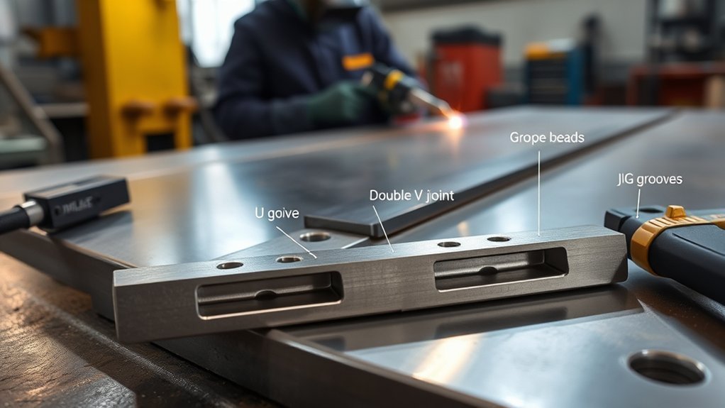
Groove weld symbols are graphical instructions used on engineering and fabrication drawings to describe groove weld requirements. The applicable symbol can communicate the required joint preparation, side of the joint to be welded, weld size, root opening, groove angle, contour, and other information.
It helps to distinguish two related terms. A weld symbol is the basic graphical shape representing a weld type, such as a V-groove or square-groove weld. A welding symbol is the complete set of information built around the reference line, including the arrow, weld symbol, dimensions, supplementary symbols, and optional tail.
In the United States, the primary symbol reference is AWS A2.4:2020, Standard Symbols for Welding, Brazing, and Nondestructive Examination. International drawings may instead follow ISO 2553:2019. The two systems share many concepts but should not be assumed to use every convention identically.
For hobby welders and fabricators, learning this notation reduces guesswork when following drawings. A separate introduction to hobby welding and fabrication can help with broader shop basics, but the drawing and applicable welding standard remain the authority for a specific joint.
Note: ISO lists a sixth-edition ISO/DIS 2553 as under development in 2026. ISO 2553:2019 remains the published international standard until a replacement is formally issued.
Groove Weld Symbol Parts: Arrow, Reference Line, and Tail
The main elements of a welding symbol work together. The arrow identifies the joint or location being referenced. The reference line carries the weld symbol and most dimensional information. The optional tail provides complementary information such as a welding process, specification, procedure, or other reference when needed.
| Element | Primary function |
|---|---|
| Arrow | Points to the joint or joint member associated with the welding requirement. |
| Reference line | Carries the weld symbol, dimensions, supplementary symbols, and side-of-joint information. |
| Tail | Carries process, specification, procedure, or other complementary information when required. |
Understanding the notation is separate from choosing the actual welding process. For broader equipment and process background, see this guide to welding processes and beginner welders.
Arrow Side and Other Side
Under AWS A2.4 conventions, the side of the joint to which the arrow points is the arrow side. Weld information placed below the reference line applies to that side. Information placed above the reference line applies to the other side.
This relationship does not change simply because the drawing arrow points left, right, upward, or downward on the page. The arrow locates the joint; the position of the weld information relative to the reference line tells you which side receives the requirement.
For certain asymmetrical groove preparations, especially a single-bevel or J-groove, the arrow can also identify which member of the joint requires preparation. A break in the arrow may be used when needed to identify the member that must be beveled or otherwise prepared.
Reference Line Placement
The reference line is the organizing element of the welding symbol. Basic weld symbols and their dimensions are positioned on or around it according to the applicable standard. AWS drawings can also use multiple reference lines when separate operations or sequences need to be communicated.
Do not interpret the reference line in isolation. A correct reading considers the arrow, groove symbol, dimensions, supplementary symbols, tail information, drawing notes, and any referenced welding specification or procedure.
Tail and Process Notes
The tail is optional. When used, it can identify a welding process, specification, welding procedure, examination requirement, or another reference that does not belong in the basic symbol area.
A missing tail does not mean that the welder may choose every parameter freely. The drawing can still be governed by a welding procedure specification (WPS), project specification, code, material requirement, or other document.
AWS vs. ISO Welding-Symbol Conventions
A major source of confusion is assuming that every drawing worldwide follows the same side-designation system. AWS A2.4 is widely used in the United States, while ISO 2553 is used internationally. ISO 2553 recognizes more than one system for identifying the arrow side and other side, including single-reference-line and dual-reference-line approaches.
| Reference | What to know |
|---|---|
| AWS A2.4:2020 | AWS convention places arrow-side information below the reference line and other-side information above it. |
| ISO 2553:2019 | Defines symbolic representation of welded joints and recognizes different systems for designating the arrow side and other side. |
Pro Tip: Before interpreting a production drawing, identify which welding-symbol standard the drawing or project specification invokes. Do not automatically apply AWS placement rules to an ISO drawing—or vice versa.
Common Groove Weld Types and Symbols
Groove welds are classified partly by the shape of the joint preparation. The preparation affects root access, weld-metal volume, machining effort, distortion, and the welding procedure that may be used.
| Groove type | Typical preparation | Key point |
|---|---|---|
| Square groove | Edges are essentially square, with a specified root opening when required. | Simple preparation, but suitable thickness and penetration capability depend on the procedure and joint requirements. |
| V-groove | Both members are prepared to form a V. | Provides open access to the root but can require substantial weld metal in thick sections. |
| Bevel groove | One member is beveled while the other remains square. | The arrow may be significant because it can identify the member requiring preparation. |
| U-groove | Both edges receive a curved, concave preparation. | Can reduce weld-metal volume in heavy sections but usually requires more machining. |
| J-groove | One member receives a curved J-shaped preparation while the other remains square. | Like a bevel groove, the prepared member can be important to arrow interpretation. |
| Flare-V groove | Created by two curved or rounded surfaces. | Common where member geometry naturally forms the groove. |
| Flare-bevel groove | A curved member meets a relatively flat member. | Groove geometry comes from the shape of the parts rather than conventional edge beveling. |
Many of these preparations can also appear in double-sided forms. A double-V or double-U preparation, for example, distributes welding between both sides of the joint. That can reduce the weld-metal volume and distortion compared with a large single-sided preparation, although it also requires access to both sides.
Material thickness is one factor in joint design, but the correct groove cannot be selected from thickness alone. Process capability, welding position, accessibility, material, procedure qualification, loading, and governing code all matter. For equipment-oriented background, see this guide to multi-process welder capabilities.
How to Read Groove Weld Dimensions
Groove-weld dimensions are interpreted primarily by their position around the weld symbol. Do not expect every drawing to print letters such as D, G, or T beside the dimensions. Those letters are often used in explanations and diagrams, while actual production symbols rely on standardized placement.
For common AWS groove symbols, the information can include:
- Depth of preparation or depth of bevel: shown to the left of the groove symbol when required.
- Groove-weld size: also associated with the left side of the symbol; when both preparation depth and groove-weld size are specified, the weld-size value may appear in parentheses.
- Root opening: shown in the groove-symbol area when required.
- Groove or included angle: shown with the groove symbol when the angle must be specified.
- Contour and finishing information: supplementary symbols may specify the required final contour and, where applicable, a finishing method.
Miller’s welding-symbol guide provides graphical examples of V-, bevel-, U-, J-, flare-V-, and flare-bevel groove symbols and shows how common groove dimensions are positioned.
The location of a dimension is part of its meaning. Read the number together with the groove symbol rather than treating it as an isolated measurement.
Electrical setup such as AC versus DC is not encoded simply by the groove dimensions. That belongs to the welding process and procedure requirements. For separate equipment background, see this guide to AC/DC welding functionality.
How to Read a Groove Weld Symbol Step by Step
- Identify the governing standard. Determine whether the drawing follows AWS A2.4, ISO 2553, or another specified system.
- Follow the arrow to the joint. Confirm which joint or member the callout refers to.
- Identify the required side. Under AWS conventions, below the reference line means arrow side; above means other side.
- Identify the groove symbol. Determine whether it is square, V, bevel, U, J, flare-V, flare-bevel, or a double-sided configuration.
- Read the dimensions and supplementary symbols. Check preparation depth, weld size, root opening, groove angle, contour, backing, melt-through, and other specified details.
- Read the tail and drawing notes. Verify any process, procedure, specification, sequence, or inspection requirement before fabrication begins.
Warning: A welding symbol is not a substitute for the approved drawing, WPS, applicable code, or safe welding practices. Welding can expose workers to fumes, ultraviolet radiation, burns, fire, electrical hazards, and other risks. Follow the employer’s safety program and applicable welding-safety requirements.
Groove Weld Penetration: CJP vs. PJP
Complete joint penetration (CJP) and partial joint penetration (PJP) describe how far the weld is required to penetrate through the joint thickness. They should not be treated as simple “strong” versus “weak” labels.
Complete Joint Penetration
A CJP groove weld has weld metal extending through the thickness of the joint as required by the applicable joint definition and specification. Achieving that result may require appropriate edge preparation, root opening, backing, back gouging, welding from both sides, or another qualified procedure.
CJP can provide joint continuity needed for many highly loaded applications, but the letters “CJP” do not independently guarantee maximum strength or acceptable workmanship. Base metal, filler metal, joint design, loading, procedure qualification, weld quality, and the governing code still determine whether the completed joint is suitable.
- Verify the specified joint preparation.
- Control root opening and alignment.
- Follow the approved welding procedure.
- Use the required inspection and acceptance criteria.
Partial Joint Penetration
A PJP groove weld intentionally does not extend through the entire joint thickness. Its required weld size and preparation are selected by the designer according to the load path, material, joint geometry, applicable code, and service conditions.
PJP is not automatically a defective or inferior weld. It can be the correct engineered choice when complete penetration is unnecessary. The important requirement is that the finished weld matches the specified size, quality, procedure, and acceptance criteria.
Product specifications sometimes discuss the material thickness range of welding machines, but machine capacity alone does not determine whether a groove weld qualifies as CJP or PJP.
Groove Weld Backing, Back Welds, Back Gouging, and Melt-Through
These terms are frequently confused because they all relate to the root side of a groove weld. Their functions and sequence are different.
| Term | Meaning |
|---|---|
| Backing | Material or a backing arrangement placed at the root to support or help control molten weld metal as required by the joint procedure. |
| Backing weld | A weld used as backing for the groove weld and therefore made before the weld it supports. |
| Back weld | A weld deposited on the back side of a single-groove weld after welding has been performed from the first side. |
| Back gouging | Removal of weld and/or base metal from the reverse side to expose suitable metal before welding from that side when the procedure requires it. |
| Melt-through | A supplementary symbol indicating the required root-side condition associated with complete penetration and visible root reinforcement in the applicable joint configuration. |
A backing symbol may also indicate whether backing is to be removed after welding. The correct backing material and removal requirements come from the drawing, welding procedure, specification, or governing code rather than from a generic rule.
Electrode classification can also matter to a qualified procedure, but selecting low-hydrogen or other welding electrodes does not change the meaning of the welding symbol itself.
Groove Weld Fit-Up and Inspection Checks
A correctly drawn symbol can still produce a poor joint if the parts are not fitted as specified. Preweld inspection should compare the assembled joint with the drawing, WPS, and applicable tolerances before the arc is struck.
Important checks can include:
- Groove angle and bevel angle where specified.
- Root opening and root face.
- Joint alignment and mismatch.
- Backing type, position, and condition where required.
- Joint cleanliness, including removal of contaminants that interfere with the procedure.
- Overall assembly dimensions and tack-weld condition.
Welding gauges, scales, straightedges, and other measuring tools can help verify dimensions. For additional equipment background, see this overview of welding equipment for home use.
After welding, inspection requirements depend on the applicable code, specification, contract, and service conditions. Visual inspection may be sufficient for some characteristics, while other joints can require additional nondestructive examination. Do not infer an acceptance criterion solely from the groove symbol.
Common Groove Weld Symbol Mistakes to Avoid
Most symbol-reading mistakes come from skipping one part of the callout or assuming that familiar shop practice overrides the drawing.
- Reading the arrow direction but ignoring symbol placement: under AWS, above versus below the reference line establishes other-side versus arrow-side information.
- Confusing a bevel groove with a V-groove: a bevel groove prepares one member; a V-groove prepares both.
- Ignoring which member is prepared: the arrow can have special significance for bevel and J grooves.
- Missing root opening or groove angle: small dimensional changes can affect root access, weld volume, and the qualified joint configuration.
- Treating CJP as a universal strength rating: CJP describes penetration, not the complete structural design.
- Confusing backing weld and back weld: their sequence and purpose are different.
- Assuming the symbol replaces the WPS: the welding procedure still controls process variables and technique within its qualified range.
- Mixing AWS and ISO conventions: first determine which standard the drawing uses.
Welder controls such as arc-control features can affect how a process runs, but they cannot correct an incorrectly interpreted drawing or an off-spec joint preparation.
Frequently Asked Questions
What are the different types of groove weld symbols?
Common basic groove weld symbols include square, V, bevel, U, J, flare-V, and flare-bevel grooves. Several can also be specified as double-sided preparations. The symbol represents the required weld or joint-preparation form, while dimensions and supplementary symbols provide additional requirements.
How do you interpret weld symbols?
Start by identifying the applicable standard, then follow the arrow to the joint. Determine the required side from the reference-line convention, identify the basic weld symbol, read dimensions and supplementary symbols, and finally check the tail, drawing notes, WPS, and applicable specification.
What are the five types of groove welds?
There is no need to limit groove welds to a universal list of five. Square, V, bevel, U, J, flare-V, and flare-bevel groove symbols are all commonly recognized in AWS welding-symbol guidance, and several have single- and double-sided forms.
What are the different types of seam weld symbols?
Seam weld symbols are a separate category from groove weld symbols. Under AWS A2.4, seam-weld callouts can communicate information such as weld size or strength, length, spacing or pitch where applicable, the number or extent of welds, and process information. They should be interpreted using the dedicated seam-weld provisions of the applicable symbol standard rather than groove-weld rules.
Sources
- American Welding Society — AWS A2.4:2020 — primary AWS standard for welding, brazing, and nondestructive-examination symbols.
- American Welding Society — Arrow-Side and Other-Side Symbol Guidance — supports AWS placement rules above and below the reference line.
- ISO 2553:2019 — international rules for symbolic representation of welded joints.
- ISO/DIS 2553, Edition 6 — identifies the newer edition currently under development.
- Miller — How to Read and Understand Weld Symbols — practical examples of groove types, dimensions, backing, and melt-through symbols.
- OSHA — Welding, Cutting, and Brazing Hazards and Solutions — supports the welding-safety guidance.
Conclusion
Groove weld symbols turn joint requirements into a compact drawing language, but each part of the callout has a specific job. Read the arrow, reference-line position, groove type, dimensions, supplementary symbols, and tail together. Distinguish CJP from PJP and backing from back welding, and always confirm whether the drawing follows AWS, ISO, or another specified standard. Correct interpretation, accurate fit-up, an approved welding procedure, and the required inspection criteria are what turn the symbol into a weld that matches the design.