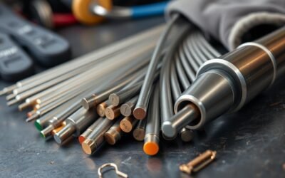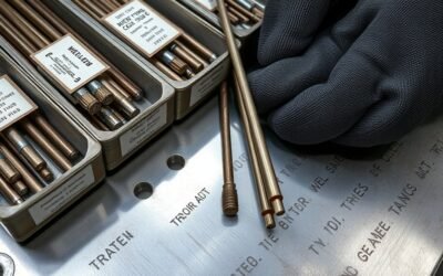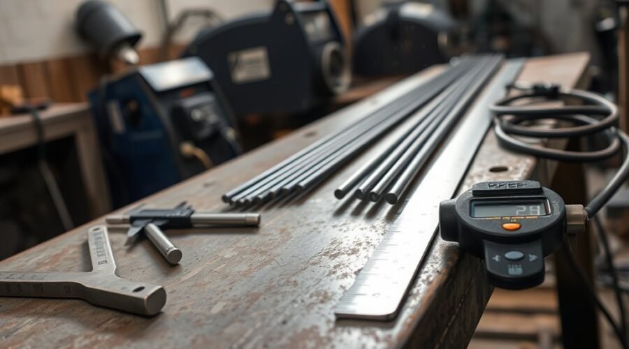
Welding rod size is the diameter of a stick-welding electrode, but diameter alone does not determine the correct amperage or the thickness of steel it can weld. Electrode classification, joint design, welding position, polarity, machine output, and the manufacturer’s operating range all matter. Common SMAW electrode diameters include 3/32″, 1/8″, and 5/32″, with smaller and larger sizes available for specific applications.
Quick Answer
For stick welding, 3/32″ electrodes are useful for lighter material and lower amperage, 1/8″ is a common general-purpose size, and 5/32″ suits higher-current work. However, amperage depends on electrode type as well as diameter, so always use the range printed on the electrode package or manufacturer data sheet.
Key Takeaways
- Stick-welding rod size refers to the diameter of the electrode’s metal core.
- Common SMAW diameters include 3/32″ (2.4 mm), 1/8″ (3.2 mm), and 5/32″ (4.0 mm).
- There is no single amperage range that applies to every electrode of the same diameter; E6011, E6013, E7018, and other classifications differ.
- Thin material generally benefits from smaller electrodes and controlled heat, while thicker joints may use larger electrodes, bevels, and multiple passes.
- For structural or code work, follow the approved welding procedure, electrode manufacturer data, and applicable welding standard rather than a generic chart alone.
Warning: Arc welding can cause electric shock, burns, eye injury, fires, and exposure to hazardous fumes. Wear suitable welding PPE, provide adequate ventilation, remove nearby combustibles, and follow the welder manual, electrode safety information, and applicable workplace or welding-code requirements.
How Welding Rod Sizes Are Measured
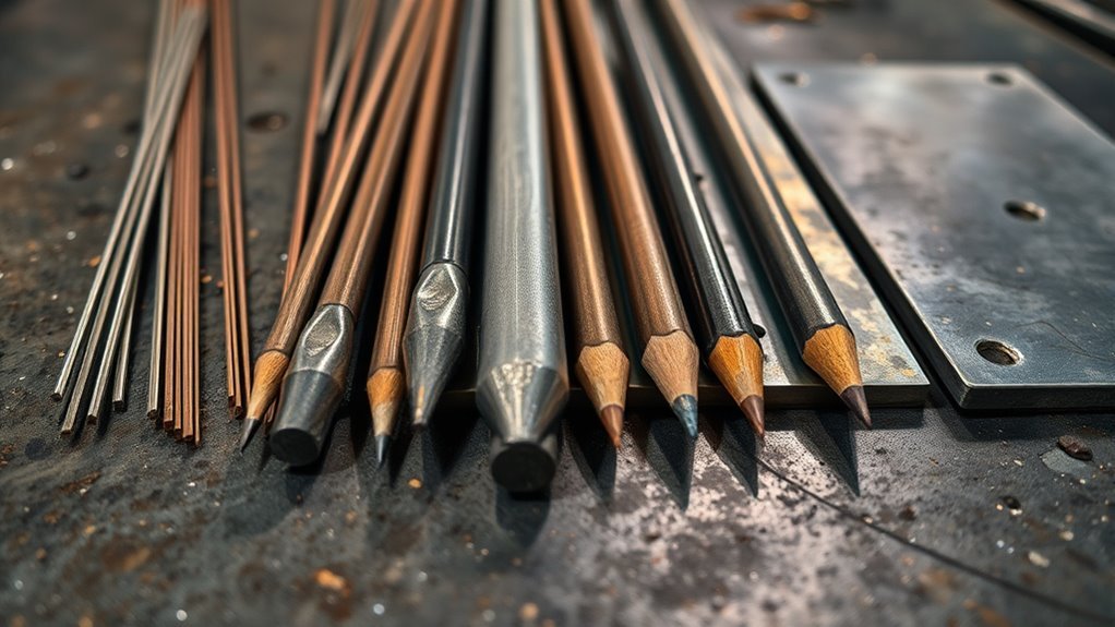
For shielded metal arc welding (SMAW), commonly called stick welding, rod size refers to the diameter of the electrode core. It is usually listed in inches in the United States and millimeters in metric specifications.
| Nominal diameter | Metric equivalent | Typical use |
|---|---|---|
| 1/16″ | 1.6 mm | Very light work where that diameter is available for the selected electrode type |
| 5/64″ | 2.0 mm | Light-gauge work, commonly available in some E6013 products |
| 3/32″ | 2.4 mm | Light material, root passes, and lower-current welding |
| 1/8″ | 3.2 mm | Common general-purpose stick-welding size |
| 5/32″ | 4.0 mm | Higher deposition and heavier fabrication where machine output allows |
| 3/16″ | 4.8 mm | Higher-current work, often on heavier joints |
| 1/4″ | 6.4 mm | High-current, high-deposition applications using suitable electrodes and equipment |
Diameter influences the amount of current the electrode can carry and how much filler metal it deposits, but it does not independently determine penetration. Electrode coating, polarity, joint design, travel speed, arc length, and welding technique also affect the finished weld.
Electrode length is a separate specification. Length affects how long the electrode can be used before replacement and may affect handling, but it should not be used as the primary basis for selecting a rod for a particular metal thickness.
Note: This article focuses mainly on SMAW or stick electrodes. MIG/GMAW and flux-cored welding use continuously fed wire, while TIG/GTAW uses a nonconsumable tungsten electrode and, when needed, a separate filler rod.
Welding Rod Size Chart
A useful welding rod size chart should separate diameter from electrode classification. Two electrodes with the same diameter can require different current because their coatings, arc characteristics, and intended applications are different.
Example Amperage Ranges by Electrode Type
| Electrode | Diameter | Example amperage range | Important note |
|---|---|---|---|
| E6011 | 3/32″ | 60–90 A | Representative Hobart 335A AC/DCEP range |
| E6011 | 1/8″ | 80–125 A | Representative Hobart 335A AC/DCEP range |
| E6011 | 5/32″ | 130–160 A | Representative Hobart 335A AC/DCEP range |
| E6013 | 3/32″ | 70–105 A DC / 75–115 A AC | Representative Lincoln Fleetweld 37 range |
| E6013 | 1/8″ | 100–135 A DC / 110–140 A AC | Representative Lincoln Fleetweld 37 range |
| E6013 | 5/32″ | 145–180 A DC / 160–200 A AC | Representative Lincoln Fleetweld 37 range |
| E7018 | 3/32″ | 80–100 A | Approximate Hobart guidance |
| E7018 | 1/8″ | 90–150 A | Approximate Hobart guidance |
| E7018 | 5/32″ | 110–230 A | Approximate Hobart guidance |
| E7018 | 1/4″ | 270–380 A | Approximate Hobart guidance; requires a high-output machine |
Electrode diameter gives you a starting point, but the electrode manufacturer’s operating range is the number that should control the final amperage setting.
These ranges are examples, not universal limits. Different brands and electrode formulations can specify different values even when the AWS classification and diameter appear similar.
Match Rod Size to Metal Thickness
Base-metal thickness is an important starting point, but there is no reliable rule saying the electrode must equal one-half of the workpiece thickness. The best diameter depends on the electrode classification, joint design, weld size, position, required penetration, and whether the weld will be made in one pass or several.
Thickness-to-Rod Match
| Base metal / joint | Practical starting diameter | Selection notes |
|---|---|---|
| Light sheet and thin sections | 5/64″ or 3/32″ | Use an electrode type intended for light material, low enough current to control heat, and short welds where needed to limit distortion. |
| Around 1/8″ | 3/32″ or 1/8″ | Either may work depending on electrode classification, joint fit-up, position, and desired weld size. |
| Around 1/4″ | 1/8″ or 5/32″ | Joint preparation and the number of passes often matter more than simply moving to the largest available electrode. |
| Heavy plate | 1/8″, 5/32″, or larger where appropriate | Use bevels, root openings, preheat when required, and multiple passes according to the welding procedure. |
A 1/8″ electrode is not limited to a specific maximum plate thickness. It can be used on substantially thicker material when the joint is properly prepared and the weld is built with multiple passes. Likewise, choosing a 1/4″ rod merely because the plate is thick may be inappropriate if the machine cannot supply the required current or the welding position does not suit that electrode.
Prevent Burn-Through
Burn-through occurs when heat input is too high for the joint, especially on thin material or wide root openings. Electrode diameter is only one part of the solution.
- Choose an electrode type and diameter suited to light material.
- Stay within the manufacturer’s recommended amperage range.
- Reduce heat input when the puddle becomes excessively fluid.
- Use a tighter fit-up where the joint design allows.
- Use short welds or skip/stitch techniques when distortion control is important.
- Increase travel speed carefully if the puddle is overheating the edge.
Pro Tip: When you are unsure between two rod sizes, start with the smaller practical diameter and the electrode manufacturer’s recommended current. It is usually easier to increase current or move up one size after a test bead than to repair a burned-through joint.
Choose the Right Electrode Type
Electrode classification matters as much as diameter. The coating controls arc characteristics, penetration profile, slag behavior, suitable current type, position capability, and hydrogen characteristics.
Electrode Type Basics
For common carbon-steel SMAW electrodes, the AWS designation gives useful information. In a designation such as E6011 or E7018:
- E identifies an electrode.
- The first two digits, such as 60 or 70, relate to minimum tensile-strength classification in thousands of pounds per square inch.
- The next digit identifies qualified welding-position capability. A 1 indicates all-position capability.
- The final digit relates to coating characteristics and suitable welding current. Check the electrode specification or manufacturer literature for the exact requirements.
| Electrode | General characteristics | Common uses |
|---|---|---|
| E6010 | Deep-penetrating, fast-freeze cellulosic electrode; typically used with DCEP | Pipe, root passes, field work, and joints needing a digging arc |
| E6011 | Fast-freeze, penetrating cellulosic electrode; commonly supports AC and DCEP | Repair, fabrication, galvanized/coated steel applications, and jobs where surface preparation is less than ideal |
| E6013 | Softer arc with relatively easy operation and lower penetration than digging electrodes | Clean sheet metal, light fabrication, maintenance, and smaller AC welders |
| E7018 | Low-hydrogen electrode with strong mechanical properties and controlled hydrogen characteristics | Structural fabrication, heavy equipment, multiple-pass welds, and applications requiring low-hydrogen procedures |
Stick Rods vs MIG, Flux-Core, and TIG Sizes
| Process | Consumable | Common diameter examples |
|---|---|---|
| SMAW | Flux-coated stick electrode | 3/32″, 1/8″, 5/32″, with smaller and larger sizes available |
| GMAW / MIG | Continuous solid wire electrode | 0.023″, 0.030″, 0.035″, 0.045″ are common examples |
| FCAW | Continuous flux-cored wire electrode | 0.030″, 0.035″, 0.045″ and larger industrial wires |
| GTAW / TIG | Nonconsumable tungsten electrode plus optional filler rod | Tungsten and filler sizes are selected separately for the application |
Match Rod To Metal
Start with the base-metal type and required weld properties, not diameter alone. For mild steel, E60- and E70-series electrodes may both be suitable in many applications, but the correct classification depends on required strength, penetration, service conditions, procedure requirements, and hydrogen control.
E6010 and E6011 provide a more digging arc than E7018 and can be useful where penetration and fast-freeze puddle characteristics are needed. E7018 is chosen in many structural applications because of its low-hydrogen characteristics and mechanical properties, not simply because the plate is thick.
Clean the joint whenever practical. Although electrodes such as E6010 and E6011 tolerate poorer surface conditions better than some alternatives, excessive rust, paint, grease, moisture, and mill scale can still contribute to weld defects.
Pick By Welding Position
Welding position affects both electrode classification and diameter. Smaller electrodes are often easier to control vertically or overhead because they create a smaller molten pool, but diameter alone does not determine whether an electrode is suitable for those positions.
Check the electrode classification and product data first. Many E6011 and E7018 electrodes are designed for flat, horizontal, vertical, and overhead welding, while some high-deposition electrodes are restricted mainly to flat and horizontal work.
Out-of-position welding often benefits from lower current than flat-position welding. The exact reduction is product- and procedure-specific rather than a universal 5% or 10%. Adjust within the manufacturer’s permitted range while watching puddle control and fusion.
Match Amperage to Rod Size
The correct amperage depends primarily on electrode type, diameter, polarity, position, and application. Generic charts can provide a starting point, but the package or manufacturer data sheet should be the final reference.
A useful setup sequence is:
- Identify the base metal and required weld properties.
- Select the correct electrode classification.
- Confirm that the electrode is suitable for the welding position.
- Choose a diameter that fits the joint size, access, and machine output.
- Set the required AC/DC polarity.
- Start near the manufacturer’s recommended or mid-range amperage.
- Run a test bead and fine-tune current in small increments.
Signs the Amperage Is Too Low
- The electrode repeatedly sticks to the work.
- The arc is difficult to maintain.
- The bead sits high and does not wet into the toes.
- Fusion or penetration appears inadequate.
Signs the Amperage Is Too High
- Spatter increases sharply.
- The puddle becomes difficult to control.
- Undercut develops along the weld toes.
- The electrode burns excessively fast.
- Thin material overheats or burns through.
Adjust current gradually rather than jumping far outside the electrode’s published range. Arc length, travel speed, work angle, and electrode condition can cause symptoms that resemble incorrect amperage, so consider the complete setup.
Choose Rod Size for Different Positions
Gravity changes puddle behavior, so the ideal electrode diameter for flat welding may feel too large in vertical or overhead work.
| Position | Rod-size approach | Current guidance |
|---|---|---|
| Flat | Larger diameters can be practical when higher deposition is needed and the machine supports them. | Use the manufacturer’s normal operating range. |
| Horizontal | Common 3/32″, 1/8″, and suitable 5/32″ electrodes may be used depending on classification and joint. | Control current to prevent the puddle from sagging toward the lower plate. |
| Vertical-up | Smaller diameters often improve puddle control, but qualified larger electrodes may also be used. | Current is often reduced from the flat-position setting within the manufacturer’s permitted range. |
| Overhead | Smaller electrodes commonly make the molten pool easier to control. | A lower setting than flat welding is often useful, but follow product and procedure guidance. |
Do not assume that every 1/16″ or 3/32″ electrode is automatically suitable for overhead welding. Position capability is determined by the electrode classification and product specification.
How Rod Size Changes Bead Shape
Electrode diameter affects filler-metal deposition and the size of the puddle. With the correct current, a smaller electrode usually produces a smaller bead and gives the operator more control in tight joints or light material. Larger electrodes can deposit more metal per unit time and produce larger weld beads.
- A smaller diameter can make it easier to control heat on light material.
- A larger diameter generally supports greater deposition at higher current.
- Electrode classification and polarity strongly influence penetration, so diameter alone does not predict penetration depth.
- Increasing amperage can flatten and widen a bead, but excessive current may cause undercut, spatter, or burn-through.
- Travel speed and arc length also change bead width and reinforcement.
Rod diameter controls how much current and filler metal the electrode can practically carry, while electrode type and technique determine how that energy is delivered into the joint.
Common Welding Rod Size Mistakes
The most common sizing mistake is choosing a rod from a generic diameter chart without first identifying the electrode classification and welding procedure.
- Using one amperage range for every electrode: E6011, E6013, E7018, and other products can have substantially different operating ranges.
- Choosing the largest rod for thick plate: thick joints often require proper beveling and multiple passes rather than one oversized electrode.
- Using too large a rod on thin metal: this can make heat and puddle control difficult.
- Ignoring polarity: some electrodes require or perform best on a specific AC/DC setup.
- Ignoring welding position: an electrode suitable for flat welding may not be appropriate for vertical or overhead use.
- Exceeding machine capability: large electrodes may require more amperage or duty cycle than a small welder can provide.
- Trying to fix technique only with amperage: arc length, travel speed, electrode angle, fit-up, and surface condition also affect bead quality.
Consider Welder Output and Duty Cycle
A welding machine must be able to supply the current required by the selected electrode. A machine rated for 200 amps does not necessarily run continuously at 200 amps; its duty cycle determines how long it can operate at a stated output before it must cool.
Large electrodes such as 3/16″ or 1/4″ can require substantial current, so check both the welder’s output range and duty-cycle rating. For home or light fabrication machines, a smaller electrode may allow longer practical welding periods and better arc control.
Machine amperage should not be converted directly into a maximum plate thickness. A properly prepared multipass weld can join material much thicker than the diameter of the electrode, provided the welder, consumable, joint design, and procedure are suitable.
Joint Design and Multiple Passes Matter
Thick steel is not normally welded simply by selecting a rod whose diameter tracks the plate thickness. Groove angle, root opening, root face, backing, weld size, preheat, interpass temperature, and the number of passes may all be specified by the welding procedure.
For example, a 1/8″ or 5/32″ electrode can build a large weld through several controlled passes. This approach can provide better access to the joint root and better control of bead placement than attempting to fill the entire joint with one very large electrode.
Note: Structural, pressure-containing, load-bearing, or code-regulated welds should follow an approved welding procedure specification rather than informal thickness charts.
Welding Rod Storage and Maintenance Tips
Electrode storage is not the same for every rod classification. Moisture can alter flux behavior and, for low-hydrogen electrodes, can defeat the reason the electrode was selected in the first place.
Low-Hydrogen Electrodes
E7018 and other low-hydrogen electrodes require controlled storage after their hermetically sealed package is opened. Manufacturer guidance commonly specifies heated rod-oven storage for these products. For example, Lincoln recommends approximately 250–300°F (120–150°C) for opened low-hydrogen electrodes.
Do not invent your own rebaking temperature or use a household oven. Reconditioning requirements depend on the specific product and applicable welding code.
Cellulosic Electrodes
E6010 and E6011 are different. Their coatings are intentionally formulated with moisture characteristics needed for proper operation. They should generally be stored dry at room temperature and should not be treated like low-hydrogen E7018 electrodes.
- Keep electrodes clean and protected from liquid water, oil, grease, and physical damage.
- Follow the storage instructions printed on the electrode package or manufacturer data sheet.
- Inspect coatings for cracks, broken flux, contamination, or obvious moisture damage.
- Keep different electrode classifications clearly separated to avoid using the wrong rod.
- Follow stricter exposure and storage limits when a welding code or procedure requires them.
Frequently Asked Questions
What Are the Different Sizes of Welding Rods in Order?
Common stick-electrode diameters progress through sizes such as 1/16″, 5/64″, 3/32″, 1/8″, 5/32″, 3/16″, 7/32″, and 1/4″. Not every electrode classification is manufactured in every diameter. For general SMAW work, 3/32″, 1/8″, and 5/32″ are among the most common sizes.
How Thick Can a 200 Amp Stick Welder Weld?
There is no single maximum plate thickness for a 200-amp stick welder. A 200 A machine can run many common 1/8″ and 5/32″ electrodes, but the thickness it can join depends on electrode type, joint preparation, number of passes, duty cycle, base metal, and the required weld size. Thick material is commonly welded with multiple passes rather than one oversized bead.
Should I Use 6011 or 7018?
Use E6011 when you need a penetrating, fast-freeze electrode that works well for repair, field welding, and surfaces that are not perfectly clean. Use E7018 when low-hydrogen characteristics, smooth deposits, and structural mechanical properties are important. The welding procedure, base metal, position, and required properties should decide the final choice.
What Is the Amperage Range for Different Welding Rod Sizes?
There is no universal amperage range based only on rod diameter. For example, a 1/8″ E6011 may have a different range from a 1/8″ E6013 or E7018. Use the amperage range supplied by the electrode manufacturer, then adjust within that range for welding position, joint design, and puddle behavior.
Is a 1/8-Inch Welding Rod Bigger Than a 3/32-Inch Rod?
Yes. A 1/8″ electrode is 0.125 inch in diameter, while a 3/32″ electrode is 0.09375 inch. The 1/8″ rod generally carries more current and deposits more filler metal, but the exact operating range still depends on electrode classification.
Can I Use the Same Amperage for 6011 and 7018?
Do not assume so. Even when E6011 and E7018 have the same diameter, their recommended amperage ranges can differ. Check the specific product data or electrode package for current range and polarity before welding.
Conclusion
The right welding rod size comes from matching several variables rather than relying on diameter alone. Start with the base metal and required weld properties, choose the correct electrode classification, confirm welding position and polarity, then select a practical diameter and set the amperage from the manufacturer’s data. Smaller rods generally improve control on light material and difficult positions, while larger rods can increase deposition when the joint, procedure, and machine support them. For thick material, proper joint preparation and multiple passes are often more important than choosing the largest available electrode.
Sources
- American Welding Society — AWS A5.1/A5.1M:2025, Specification for Carbon Steel Electrodes for Shielded Metal Arc Welding.
- Miller Electric — Factors for Selecting the Right Stick Electrode.
- Miller Electric — Five Steps to Improving Your Stick Welding Technique.
- Hobart Brothers — 7018 Welding Rod Amperage guidance and Hobart 335A E6011 product data.
- Lincoln Electric — Fleetweld 37 E6013 operating data and Stick Electrode Storage & Handling guidance.
- U.S. Occupational Safety and Health Administration — 29 CFR 1910.252, Welding, Cutting, and Brazing general requirements.