Slag inclusion in welding occurs when non-metallic slag becomes trapped inside the weld metal or between weld passes instead of separating from the molten pool and being removed. It is most closely associated with flux-producing processes such as SMAW/MMA, flux-cored arc welding, and submerged arc welding. The risk depends on bead shape, joint geometry, welding technique, consumable behavior, heat input, and especially cleaning between passes.
Quick Answer
Slag inclusion is trapped flux-derived material inside or between weld passes. Common causes include incomplete interpass cleaning, poor bead overlap, undercut, unsuitable electrode manipulation, incorrect travel speed or current, and joint shapes that trap slag. Prevention centers on clean passes, sound bead profiles, correct welding parameters, and inspection before the next run.
Key Takeaways
- Slag inclusion is a solid, non-metallic weld imperfection, not the same defect as porosity or lack of fusion.
- It is most common in welding processes that use flux and create a slag covering.
- Poor interpass cleaning, undercut, irregular bead shape, poor overlap, incorrect electrode angle, and unsuitable parameters can trap slag.
- Visual and penetrant testing can only reveal accessible surface conditions; radiographic or ultrasonic testing may be used for internal examination when the applicable procedure permits.
- ISO 6520-1 identifies slag inclusion as imperfection reference 301, while ISO 5817:2023 provides quality levels used to evaluate weld imperfections within its scope.
What Is Slag Inclusion in Welding?
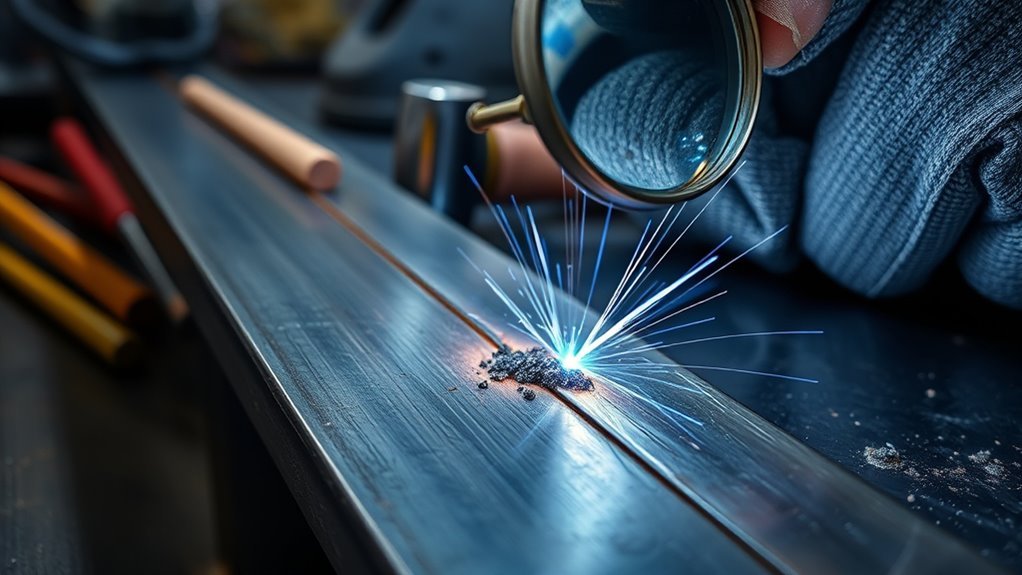
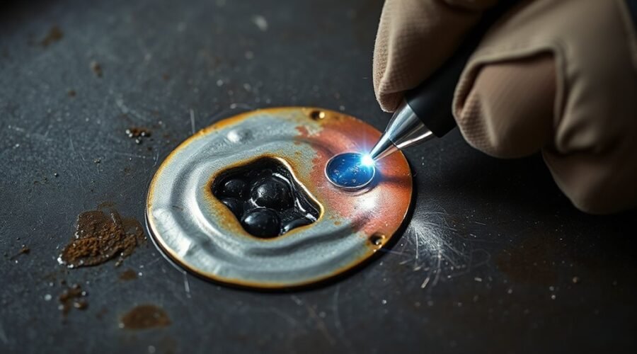
Slag inclusion is a weld imperfection in which solid non-metallic material, usually originating from flux and its reaction products, becomes trapped in the weld metal or between successive weld passes. Instead of floating to the surface and being removed, some slag remains enclosed as the metal solidifies.
Slag inclusions often appear as elongated or irregular indications. They are especially associated with flux-producing processes such as shielded metal arc welding (SMAW/MMA), flux-cored arc welding (FCAW), and submerged arc welding (SAW). Industry guidance from TWI on slag inclusions also notes that joint shape, bead overlap, welding position, flux coating, and welder technique influence the risk.
An inclusion can interrupt otherwise continuous weld metal, reduce the effective load-bearing section, and create a local stress concentration. Its actual significance depends on its dimensions, orientation, location, material, service loading, and the acceptance requirements that apply to the welded component.
Note: A weld imperfection is not automatically a rejected weld. Acceptance must be evaluated against the applicable drawing, contract, construction code, product standard, welding specification, or selected quality level.
Slag Inclusion vs. Porosity, Lack of Fusion, and Other Inclusions
Slag inclusion is sometimes grouped loosely with other weld defects, but the mechanisms are different.
| Imperfection | What It Is | Typical Mechanism |
|---|---|---|
| Slag inclusion | Trapped solid non-metallic slag | Slag remains in a pocket or between runs |
| Porosity | Gas cavities in solidified weld metal | Gas becomes trapped during solidification |
| Lack of fusion | Failure to fuse adjoining weld or base-metal surfaces | Insufficient melting, poor access, or unsuitable technique |
| Flux or oxide inclusion | Other trapped solid non-metallic material | Process residue or oxide becomes enclosed in the weld |
A slag inclusion does not itself mean that porosity is present. Multiple imperfection types can occur in the same weld when preparation or technique is poor, but each should be identified and evaluated separately.
What Causes Slag Inclusions in Welding?
Slag inclusions usually form when slag is given a place to become trapped or is not completely removed before another weld pass covers it. Common causes include incomplete interpass cleaning, unsuitable bead shape, excessive undercut, poor overlap between adjacent beads, incorrect electrode manipulation, unsuitable travel speed or current, and restricted joint access.
| Cause | How It Raises Inclusion Risk |
|---|---|
| Incomplete slag removal | Residue from one pass can be buried by the next pass. |
| Undercut or irregular bead profile | Creates narrow pockets at the weld toes where slag can remain. |
| Poor bead overlap | Leaves grooves between adjacent runs that can trap slag. |
| Incorrect electrode angle | Can produce poor sidewall fusion or an unfavorable bead profile. |
| Unsuitable current or travel speed | Can contribute to undercut, poor fusion, irregular bead shape, or premature trapping of slag. |
| Narrow or poorly prepared joint | Restricts electrode access and makes complete cleaning difficult. |
| Unsuitable or poorly handled consumable | Can change slag behavior or make removal more difficult. |
Surface contamination can also interfere with stable welding and fusion. Rust, scale, oil, paint, moisture, and debris should be removed to the degree required by the welding procedure before welding begins.
How Joint Shape and Bead Profile Trap Slag
Joint geometry is one of the most important practical factors. Slag is more likely to remain when a weld contains narrow crevices that a brush or chipping tool cannot reach.
Typical traps include deep undercut at the weld toe, a sharp groove between adjacent beads, a highly convex previous pass, narrow V-grooves with poor electrode access, and irregular multi-pass surfaces. If the next pass bridges over one of these pockets, the slag underneath can become a buried inclusion.
Pro Tip: Do not judge interpass cleaning only by the center of the bead. Check the weld toes, undercut, starts and stops, and grooves between runs, because these are common places for small pieces of slag to remain.
How Flux Type Affects Slag Inclusions
Flux chemistry affects slag fluidity, surface tension, freezing behavior, bead profile, and how easily the solidified slag releases from the weld. Those characteristics influence whether slag can reach the surface and whether the welder can remove it completely before the next pass.
The relationship is more complex than saying one flux family always produces “good” or “bad” slag. Welding position, electrode formulation, current, travel speed, joint geometry, and bead shape all interact with the flux system.
Flux Coating and Slag
In shielded metal arc welding, the electrode coating produces shielding and a slag layer that protects the hot weld metal. Ideally, the molten slag flows over the weld pool and later separates cleanly from the solidified bead.
TWI notes that basic electrodes can produce relatively fluid slag but can also develop a convex bead profile and slag that is difficult to remove from the weld toes, particularly in multi-pass welding. Rutile or acid-type coatings can behave differently depending on their formulation and the welding position.
Because formulations vary, electrode selection should follow the approved welding procedure and the consumable manufacturer’s recommendations rather than a simple assumption that more fluid slag automatically means lower inclusion risk.
Flux Fluidity and Inclusions
Slag must be fluid enough at the appropriate stage of welding to separate from the molten metal, but fluidity alone does not determine inclusion risk. The slag’s freezing rate, surface tension, bead shape, and eventual removability are also important.
Weld-pool chemistry can affect surface tension and wetting. In the MMA context described by TWI, a low-oxygen weld pool can have higher surface tension and produce a more convex bead with poorer parent-metal wetting. More oxidizing flux chemistry can lower surface tension and encourage a flatter or more concave profile.
The practical goal is not to maximize or minimize one chemical property in isolation. It is to use the specified consumable and parameters to produce a sound bead profile from which slag can escape and later be removed reliably.
How Welding Technique Creates Slag Inclusions
Welding technique has a direct effect on whether slag remains trapped. Electrode manipulation should produce adequate fusion and overlap without leaving narrow pockets between beads.
Traveling too quickly, using unsuitable current, or holding an incorrect work or travel angle can create undercut, insufficient fusion, or an irregular bead profile. Any of these conditions can leave spaces in which slag remains.
In multi-pass welds, slag must be removed before depositing the next run. Wire brushing or light chipping may be adequate when slag releases easily; localized grinding may be needed when residue is trapped in undercut, crevices, or difficult joint geometry.
The correct electrode size also matters. An electrode that is too large for a narrow preparation can restrict access to the root or sidewall, making both fusion and cleaning more difficult.
Warning: Do not raise welding current outside the qualified procedure simply to try to “burn out” trapped slag. Follow the applicable WPS and repair procedure. Grinding, gouging, and rewelding also require appropriate PPE, ventilation, fire controls, and protection of surrounding materials and equipment.
Which Welding Processes Get Slag Inclusions?
Slag inclusion is most closely associated with processes that intentionally generate flux-derived slag.
- SMAW/MMA: Electrode coating produces slag that must normally be removed between passes.
- FCAW: Flux in the tubular wire can create a slag covering whose behavior depends on the wire formulation and process parameters.
- SAW: Granular flux protects the arc and weld pool and creates slag over the deposited weld.
- Other arc processes: Non-metallic inclusions may also occur through oxides, silicates, or process contamination, although the mechanism may not be identical to classic flux-slag entrapment.
The risk increases in multi-pass welding because every completed run creates another surface that must be inspected and cleaned before it is covered.
How to Test for Slag Inclusions
The best inspection method depends on whether the suspected imperfection is open to the surface or buried inside the weld, as well as the material, thickness, geometry, specification, and required probability of detection.
| Method | Useful For | Important Limitation |
|---|---|---|
| Visual Testing | Surface condition, bead profile, undercut, cleaning, and exposed inclusions | Cannot reveal a completely buried inclusion by ordinary surface observation |
| Penetrant Testing | Discontinuities that are open to the surface | Does not detect a fully enclosed internal slag inclusion |
| Radiographic Testing | Internal volumetric and elongated density differences; slag can appear as irregular or elongated indications | Sensitivity depends on geometry, orientation, technique, thickness, and image quality |
| Ultrasonic Testing | Internal discontinuities when the material and joint are suitable for the specified ultrasonic technique | Technique selection, calibration, geometry, material, thickness, and operator procedure affect detection and sizing |
ISO 17637:2016 specifies visual testing of fusion-welded joints. For penetrant examination, ISO 3452-1:2021 covers discontinuities open to the surface and recognizes both visible systems examined under white light and fluorescent systems examined using UV-A.
For ultrasonic testing, ISO 17640:2018 remains the published ISO standard for manual ultrasonic testing within its specified scope. The applicable inspection procedure should define the method, coverage, sensitivity, evaluation, and acceptance requirements.
How to Prevent Slag Inclusions Between Passes
Preventing slag inclusions between passes starts with complete cleaning of the previous weld run and correction of any bead shape that could trap residue before another layer is deposited.
| Action | Control |
|---|---|
| Remove slag completely | Brush, chip, or grind as appropriate, paying special attention to weld toes and narrow grooves. |
| Inspect each pass | Confirm that the surface is clean and that undercut or bead irregularities will not create a slag pocket. |
| Use correct technique | Maintain the specified electrode angle, bead placement, overlap, current, and travel speed. |
| Correct problem areas | Remove trapped residue and correct unacceptable undercut or irregular profiles before covering them. |
| Follow the WPS | Stay within qualified limits for consumable, current, voltage, heat input, technique, and pass sequence where applicable. |
Cleaning between layers is especially important with multi-pass welds. Residue can remain in grooves along the weld toes even when the top of the bead appears clean. A quick inspection before restarting can prevent a small removable surface problem from becoming a buried internal imperfection.
How to Repair a Slag Inclusion
If inspection shows that a slag inclusion exceeds the applicable acceptance criteria, the repair process normally begins by determining the indication’s location and extent. The defective area is then removed using an approved method such as grinding, machining, or gouging where permitted by the repair procedure.
After removal, the excavation should be examined to confirm that the unwanted material and associated unacceptable imperfections have been removed. The area is then rewelded using the specified consumable and qualified welding procedure.
The repaired region should receive the required post-repair examination using the method specified by the governing procedure, drawing, code, or contract.
- Identify and evaluate the indication.
- Confirm that repair is required under the applicable acceptance criteria.
- Remove the unacceptable area using the approved repair method.
- Clean and inspect the excavation.
- Reweld using the applicable qualified procedure.
- Perform the required final inspection or NDT.
Grinding away visible slag without confirming the full extent of an internal indication is not a substitute for an approved repair process on critical fabrication.
What ISO 5817 Says About Slag Inclusions
ISO 6520-1:2007 provides the classification system for geometric weld imperfections and identifies slag inclusion as reference 301 within the solid-inclusion group.
ISO 5817:2023 provides quality levels for imperfections in fusion-welded joints within its stated material and process scope. It defines three quality levels: B, C, and D, with Level B representing the highest requirement on the finished weld.
ISO 5817 quality levels describe permitted imperfection limits; simply finding an inclusion does not by itself establish whether the weld is acceptable.
Evaluation therefore depends on the applicable quality level and the dimensions, location, distribution, and weld configuration covered by the standard. The required level must come from the relevant application standard, specification, drawing, contract, or other governing document rather than being selected after an imperfection is discovered.
For pressure equipment, structural work, pipelines, vehicles, or other regulated fabrication, the applicable construction or product standard may impose additional requirements. ISO 5817 should not be treated as a universal stand-alone acceptance code for every welded component.
Frequently Asked Questions
What are the most common causes of slag inclusions in welding?
Common causes include incomplete cleaning between passes, undercut, poor bead overlap, irregular or overly convex weld profiles, restricted joint access, incorrect electrode manipulation, unsuitable current or travel speed, and slag trapped in grooves at the weld toes. Consumable selection and handling can also affect slag behavior.
How do you prevent slag inclusion in welding?
Clean every pass thoroughly, maintain a bead profile that does not create slag pockets, use the specified electrode angle and travel technique, stay within the applicable WPS parameters, prepare the joint correctly, and inspect the weld toes and grooves before depositing the next pass.
What is the purpose of slag in welding?
In flux-based welding processes, slag helps protect the hot weld metal from the surrounding atmosphere, can influence weld-pool behavior and bead shape, and can provide thermal insulation as the weld cools. It should normally separate from the solidified weld so it can be removed before another pass is deposited.
What happens if you leave slag on a weld between passes?
If the next pass is deposited over remaining slag, the material can become trapped inside the weld as a slag inclusion. Residue is especially easy to trap in undercut, between poorly overlapped beads, or in narrow weld-toe grooves, so interpass cleaning is essential.
Can slag inclusion be seen from the outside?
Sometimes. Exposed slag or a surface-connected imperfection may be visible, but a slag inclusion can also be fully buried. Internal examination may therefore require radiographic or ultrasonic testing when specified and technically suitable.
Does every slag inclusion mean the weld must be rejected?
No. Whether an inclusion is acceptable depends on the governing specification or code, the required quality level, its dimensions and distribution, the weld type, and the service requirements. Critical fabrication may have stricter criteria than general workmanship applications.
Conclusion
Slag inclusion is a preventable weld imperfection when joint preparation, bead shape, interpass cleaning, consumable selection, or welding technique allow flux-derived material to remain inside the joint. The most effective controls are straightforward: produce accessible, well-fused beads, remove slag completely between passes, correct undercut or trapping pockets before covering them, and stay within the applicable welding procedure.
If an inclusion is found, its presence alone does not establish whether the weld is acceptable. Evaluate it against the applicable fabrication specification or code and the required quality level. When repair is required, remove the affected area using the approved procedure, reweld correctly, and perform the specified reinspection.
Sources
- TWI — Defects/Imperfections in Welds: Slag Inclusions — causes, flux behavior, welding technique, cleaning, and prevention.
- ISO 5817:2023 — current quality levels for imperfections in fusion-welded joints within the standard’s scope.
- ISO 6520-1:2007 — classification and designation of fusion-weld imperfections.
- ISO 17637:2016 — visual testing of fusion-welded joints.
- ISO 3452-1:2021 — general principles for penetrant testing of surface-open discontinuities.
- ISO 17640:2018 — ultrasonic testing techniques, testing levels, and assessment for welds within its stated scope.