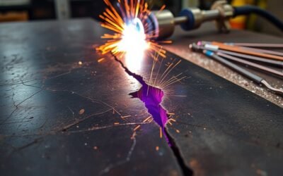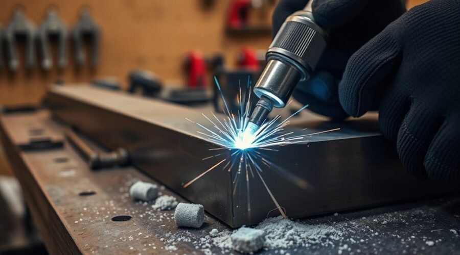
Undercut in welding is a groove melted into the base metal along the weld toe or, in some joints, at the root surface. It can reduce the effective section of the joint and create a sharp stress concentration. The most common causes are excessive current or voltage, excessive arc length, fast travel, poor torch or electrode angle, and filler metal that does not adequately fill the melted edge. Prevention and repair depend on controlling the welding procedure and judging the finished weld against the correct code, drawing, or specification.
Quick Answer
Welding undercut forms when the arc melts a groove beside the weld faster than the weld pool can fill it. Reduce the cause rather than simply adding more metal: verify current and voltage, control travel speed and arc length, use the correct torch or electrode angle, and inspect the finished weld against the governing specification.
Key Takeaways
- Undercut is a groove in the base metal at a weld toe or root that has not been completely filled with weld metal.
- Common causes include excessive current, excessive voltage or arc length, high travel speed, poor electrode or torch angle, and poor puddle control.
- There is no single allowable undercut depth for every weld; acceptance depends on the governing code, loading, joint location, material, defect length, and project requirements.
- Prevent undercut by staying within the qualified welding procedure, maintaining consistent travel and arc control, and making sure the molten pool fills both weld toes.
- Repair may involve approved blending/grinding or additional welding, followed by reinspection. Code-controlled welds should be repaired only under the applicable procedure and authorization.
What Is Undercut in Welding?
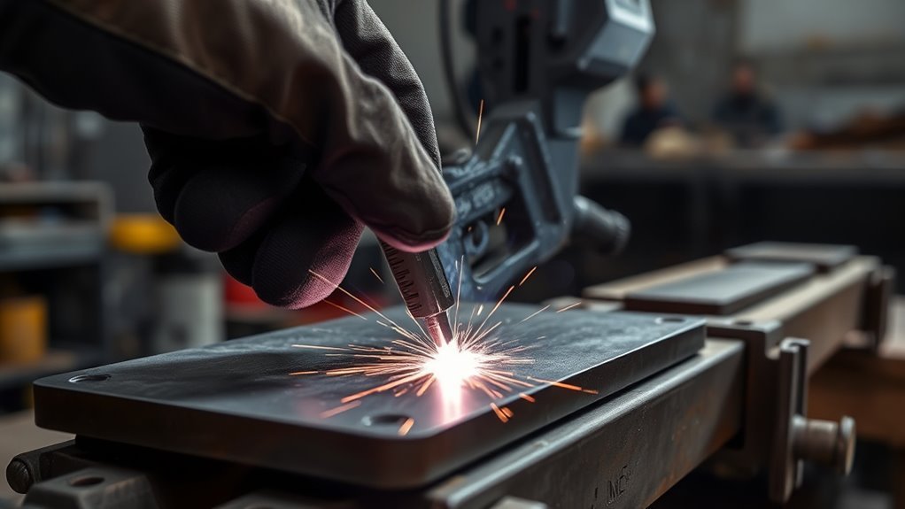
Undercut is an irregular groove or depression in the base metal at the edge of a weld that remains unfilled after the weld solidifies. TWI describes undercut as a groove at the toe of a weld run in the parent metal.
Most visible undercut occurs along one or both weld toes. Root undercut can also occur on the opposite or bore side of some joints, particularly joints welded from one side. Undercut may be continuous or intermittent.
Undercut should not be confused with lack of fusion or overlap. Lack of fusion means weld metal has not fused properly to the base metal or a previous weld pass. Overlap occurs when weld metal flows onto the base metal without properly fusing to it. Undercut instead removes or leaves a groove in the base-metal profile.
Undercut is not judged by appearance alone. Its depth, length, location, loading direction, and governing acceptance standard determine whether the weld is acceptable.
Why Undercut Weakens Welds
Undercut can reduce the effective cross-sectional area of the base metal beside the weld. More importantly, its notch-like shape creates a stress concentration at the weld toe. That matters most where the joint experiences repeated or fluctuating loads.
- Reduced section: deep undercut removes part of the base-metal thickness that should carry load.
- Stress concentration: a sharp groove concentrates stress near the weld toe.
- Fatigue sensitivity: cyclic loading can make sharp toe discontinuities more important than they would be under simple static loading.
- Corrosion exposure: an irregular groove can retain moisture, coatings may be thinner at sharp edges, and corrosion can further reduce the section in exposed service.
- Inspection failure: even a weld that appears strong may require repair when its undercut exceeds the applicable acceptance criteria.
This is why welding standards do not treat every undercut in the same way. The service condition and location of the discontinuity matter along with its measured dimensions.
What Causes Undercut in Welding?
Undercut usually develops when the arc melts the edge of the base metal but the weld pool does not deposit enough metal in that area before solidification. According to TWI and ESAB, common contributors include excessive current, excessive voltage or arc length, fast travel speed, poor torch or electrode angle, and unsuitable manipulation.
Excessive Heat Input or Arc Energy
Excessive current can make the weld pool overly fluid and melt deeply into the edge of the base metal. Excessive voltage or an unnecessarily long arc can spread the arc and wash out the weld toe. The exact relationship between current, voltage, wire feed speed, and heat input depends on the welding process, so adjustments should remain within the approved WPS or equipment manufacturer’s recommendations.
- Current too high: may aggressively melt the weld toe and make the puddle difficult to control.
- Voltage too high: can create an overly wide arc and increase the chance of edge washout in applicable processes.
- Arc too long: reduces arc concentration and can contribute to an irregular, poorly filled toe.
- Accumulated heat: on multipass welds, a very hot workpiece can change puddle behavior even when machine settings have not changed.
Poor Travel Technique
Travel speed and manipulation determine whether molten filler metal has enough time to fill the area that the arc has melted. Moving too quickly can leave a narrow groove behind the weld pool. Excessive weaving, inconsistent motion, or spending too little time at the toes can produce the same result.
Electrode and torch angles also matter. The work angle controls how the arc is directed between the joint members, while the travel angle describes the forward or backward tilt along the direction of travel. Neither angle has one universal value for every weld. Use the joint geometry, welding process, consumable instructions, and WPS as the controlling guidance.
Process-Specific Undercut Causes
| Process | Common Contributors | What to Check |
|---|---|---|
| SMAW / Stick | Current too high, arc too long, excessive travel speed, poor electrode angle, excessive weaving | Electrode amperage range, arc length, travel speed, manipulation, polarity |
| GMAW / MIG | Excess voltage, excessive travel speed, unsuitable gun angle, poor wire placement, unstable parameter balance | Voltage, wire feed speed, travel speed, contact-tip-to-work distance, gun angle, shielding setup |
| FCAW | High travel speed, excessive arc voltage, poor work angle, excessive weaving | Consumable data, WPS settings, electrode extension, travel and work angles |
| GTAW / TIG | Excess current, moving faster than filler can fill the toe, poor filler timing or torch positioning | Current, travel speed, arc length, filler placement, torch angle |
How to Prevent Undercut in Welding
Preventing undercut in welding requires a balanced combination of machine settings and technique. Do not change several variables blindly. First compare the actual welding setup with the qualified procedure or consumable manufacturer’s recommended operating range, then correct one likely cause at a time.
Proper Welding Parameters
- Verify current or wire feed speed. If the puddle is excessively fluid or the arc is aggressively washing into the toe, confirm that the setting is not above the allowed range.
- Verify voltage and arc length. Avoid an unnecessarily long or wide arc. Use the arc characteristics specified for the process and consumable.
- Check travel speed. If the arc is outrunning the puddle and leaving a groove behind it, reduce travel speed within the procedure limits.
- Confirm electrode extension or stickout where applicable. Incorrect extension changes current and arc behavior in wire processes.
- Check polarity, shielding, and consumable selection. These should match the WPS and manufacturer instructions.
Consistent Welding Technique
Keep the electrode or torch stable and direct the arc so the molten pool reaches both toes. Avoid abrupt speed changes and excessive weaving. On a weave bead, control the edges rather than racing through the toes. On a stringer bead, maintain consistent positioning and watch the trailing edge of the puddle for a groove forming behind the arc.
Clean rust, heavy scale, slag, oil, paint, and other unwanted material as required by the welding procedure. Surface contamination is more strongly associated with defects such as porosity, slag inclusion, and lack of fusion, but clean preparation also makes puddle behavior and toe condition easier to control and inspect.
Pro Tip: Watch the weld toes immediately behind the arc. If a narrow groove remains visible while the puddle moves forward, correct the cause before continuing a long weld. Catching undercut during production is usually easier than repairing a completed weld.
How to Inspect and Measure Welding Undercut
Visible undercut is normally evaluated first by visual inspection. Good lighting, a clean weld surface, and an appropriate weld gauge make shallow grooves easier to evaluate accurately.
- Clean the weld. Remove slag and loose spatter that could hide the toe.
- Inspect both toes. Follow the complete weld rather than checking only the most visible section.
- Find the deepest location. Do not judge the weld by an average-looking area.
- Measure depth with an appropriate weld or undercut gauge. Record the result when the inspection procedure requires documentation.
- Record the location and affected length. Some acceptance criteria consider both depth and extent.
- Check inaccessible surfaces as required. Root or bore-side undercut may require access from the opposite side or an inspection method specified by the governing procedure.
- Compare the measurement with the correct acceptance criteria. Use the project drawing, contract specification, WPS, governing code, and applicable edition.
Note: Visual inspection can identify surface undercut, but not every weld surface is accessible. The project specification may require additional nondestructive examination for other discontinuities or inaccessible areas.
Acceptable Undercut Depth and Limits
There is no universal maximum undercut depth that applies to every weld. Acceptance depends on the governing standard, loading condition, joint detail, material thickness, defect location, affected length, and project requirements.
For structural steel in the United States, one widely used reference is AWS D1.1/D1.1M:2025-AMD1, Structural Welding Code—Steel. Other work may instead be governed by a bridge code, pressure-vessel code, piping code, ISO standard, military specification, customer specification, or engineering drawing.
The reason one-number answers are unsafe is easy to see in the current bridge-welding requirements. The AASHTO/AWS D1.5:2025 undercut provisions apply different tolerances and treatments depending on where the undercut occurs and how the component is stressed.
Before declaring a weld acceptable or defective, determine:
- Which code, standard, drawing, or contract governs the weld.
- Which edition applies to the project.
- Whether the member is statically or cyclically loaded.
- Whether the weld toe is transverse or parallel to significant tensile stress when the governing code makes that distinction.
- The measured depth and affected length.
- The joint type and material thickness.
- Whether the project specification is more restrictive than the base code.
Warning: Do not use a generic internet depth limit to accept a structural, pressure-retaining, lifting, fatigue-critical, or safety-critical weld. Use the governing specification and obtain the required inspection or engineering approval.
Undercut Troubleshooting Guide
| What You See | Likely Cause | Correction to Check |
|---|---|---|
| Groove along both toes; puddle very fluid | Current or overall arc energy may be too high | Compare settings with the WPS/consumable range and reduce only as permitted |
| Wide, washed-out bead with toe grooves | Excess voltage or arc length | Return voltage/arc length to the specified operating range |
| Narrow groove appears behind a fast-moving arc | Travel speed too high | Slow travel within WPS limits so the pool can fill the toe |
| Undercut mainly on one side | Incorrect work angle, arc directed toward one member, or uneven manipulation | Correct torch/electrode alignment and maintain consistent toe control |
| Undercut after wide weaving | Excessive weave width or insufficient control at the toes | Use the weave limits in the WPS or switch to permitted stringer beads |
| Problem appears only after several passes | Changing joint geometry, accumulated heat, poor interpass cleaning, or altered torch access | Check interpass conditions, cleaning, bead placement, and parameter compliance |
How to Fix Undercut in a Weld
Repair starts with determining whether the undercut actually exceeds the governing acceptance criteria. An acceptable discontinuity should not automatically be ground or welded simply because it is visible. Unnecessary repair can remove additional base metal, introduce new heat cycles, distort the joint, or create another discontinuity.
At a Glance
| Time Required | Visual inspection may take only minutes; approved repair and reinspection vary by weld size, access, process, and code requirements. |
| Difficulty | Intermediate to advanced; code-controlled repairs may require a qualified welder and inspector. |
| Tools Needed | Adequate lighting, appropriate weld/undercut gauge, cleaning tools, required PPE, and—only when authorized—approved grinding and welding equipment. |
| Cost | Varies with inspection requirements, material, consumables, labor, access, and whether nondestructive examination is required. |
Repair Decision Process
- Measure the undercut. Record depth, length, and location as required.
- Check acceptance criteria. Use the applicable code, specification, WPS, drawing, and project requirements.
- If it is acceptable, follow the project’s disposition requirements. Do not automatically modify an acceptable weld.
- If it is nonconforming, identify the approved repair method. Depending on the governing rules, this may involve controlled blending/grinding, weld repair, or another engineered disposition.
- Correct the original cause. Do not repeat the same current, voltage, speed, angle, or technique that produced the undercut.
- Clean and prepare the repair area. Remove slag, oxides, oil, loose material, and other contaminants as required by the procedure.
- Perform any weld repair under the applicable WPS or approved repair procedure. Use compatible filler metal and qualified personnel where required.
- Reinspect the completed repair. Verify contour, dimensions, required weld size, and any additional examination specified for the job.
Some shallow undercut can be addressed by blending the sharp toe into a smooth contour when the governing specification permits it and sufficient base-metal section remains. Other undercut must be repaired with additional weld metal. The correct method is therefore a code and engineering decision, not simply a matter of whether the groove looks small or large.
The 2025 AASHTO/AWS D1.5 bridge-code update, for example, specifically distinguishes conditions where grinding is used to create a smooth transition from conditions requiring welding repair.
Warning: Welding and grinding can expose workers to sparks, hot metal, arc radiation, fumes, electric shock, fire, and flying particles. Follow the applicable hot-work procedure, ventilation requirements, equipment instructions, and PPE rules. OSHA provides current guidance for welding, cutting, brazing, and grinding hazards.
When to Get a Qualified Inspector or Engineer
Stop treating the issue as a simple cosmetic repair when the weld is part of a structural frame, bridge, pressure-containing system, lifting device, vehicle safety component, fatigue-critical member, or another code-controlled assembly.
A qualified welding inspector, welding supervisor, engineer, or other authorized person should determine disposition when:
- The governing acceptance criteria are unclear.
- The undercut is close to or beyond a code limit.
- The joint is cyclically or fatigue loaded.
- Grinding could reduce required base-metal thickness or weld size.
- A repair would alter a qualified weld or heat-treated component.
- Repeated undercut suggests the WPS, equipment, fit-up, consumables, or operator technique needs investigation.
- The project requires documented repair authorization or additional NDT.
Frequently Asked Questions
How Do You Prevent Undercut in Welding?
Prevent undercut by keeping welding parameters within the approved range, avoiding excessive current, voltage, arc length, and travel speed, maintaining the correct work and travel angles for the joint, controlling the puddle at both toes, and keeping the joint properly prepared. Follow the WPS and consumable manufacturer’s instructions rather than using one universal setting.
How Can Undercutting Be Prevented?
When undercut starts appearing, troubleshoot systematically. Check the approved current or wire-feed range first, then voltage or arc length, travel speed, torch or electrode angle, puddle placement, weave technique, joint access, and accumulated heat. Change one variable at a time so the actual cause becomes clear.
What Are the Common Causes of Undercut in Welding?
Common causes include excessive welding current, excessive voltage or arc length, travel speed that is too high, incorrect torch or electrode angle, excessive weaving, poor filler placement, and loss of puddle control. The dominant cause varies with SMAW, GMAW, FCAW, GTAW, welding position, joint geometry, and material.
How Should Welders Repair Undercut?
First measure the undercut and compare it with the governing acceptance criteria. If repair is required, follow the approved repair procedure. Depending on the code and condition, repair may involve permitted blending/grinding or additional weld metal. Correct the original cause before welding and reinspect the repaired area afterward.
How Much Undercut Is Acceptable in a Weld?
There is no universal allowable depth. The limit depends on the governing welding code or specification, code edition, joint type, material thickness, loading, location of the undercut, and sometimes its accumulated length. Check the project requirements before accepting or repairing the weld.
Can Undercut Be Removed by Grinding?
Sometimes. Certain specifications permit controlled grinding or blending to remove the sharp notch and create a smooth transition, provided required base-metal and weld dimensions remain intact. Other conditions require weld repair instead. Do not grind a code-controlled weld until the applicable repair requirements are known.
Conclusion
Undercut in welding is more than a cosmetic groove. It can reduce the effective base-metal section and create a stress concentration at the weld toe, particularly important in cyclic or fatigue-loaded joints. The most effective prevention is to control current, voltage or arc length, travel speed, electrode or torch position, and puddle placement within the approved welding procedure.
When undercut is found, measure it before deciding what to do. Acceptance is governed by the applicable code, specification, drawing, loading condition, and joint details—not by one universal depth limit. If repair is required, use the approved method, correct the cause that produced the undercut, and reinspect the finished weld.
Sources
- TWI — Geometric Shape Imperfections: Undercut — definition, causes, acceptance principles, and avoidance.
- American Welding Society — AWS D1.1/D1.1M:2025-AMD1 — current Structural Welding Code—Steel reference.
- American Welding Society — 2025 D1.5 Undercut Tolerances and Treatments — code-dependent acceptance and repair examples.
- ESAB — The Welder’s Guide to Defects and Remedies — common undercut causes and process corrections.
- OSHA — Welding, Cutting, and Brazing: Hazards and Solutions — welding, grinding, PPE, fume, electrical, and hot-work safety.