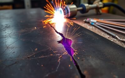
A weld troubleshooting guide works best when you identify the visible symptom first, then check the variables most likely to cause it: joint preparation, material cleanliness, technique, machine settings, electrical connections, wire or electrode delivery, and shielding. Porosity, lack of fusion, undercut, burn-through, spatter, cracking, and irregular bead shape can look similar at first, so change one variable at a time and make a test weld before deciding the problem is fixed.
Quick Answer
To troubleshoot a bad weld, identify the defect first, then verify clean metal, correct polarity, sound electrical connections, proper shielding, suitable wire or electrode, and manufacturer-recommended parameters. Adjust one setting at a time, make a test weld, and inspect again. Structural or code-regulated welds may require qualified inspection and nondestructive testing.
Key Takeaways
- Start with visual inspection to identify porosity, undercut, cracks, lack of fusion, burn-through, overlap, spatter, or an abnormal bead profile.
- Check torch or electrode angle, travel speed, arc position, stickout or arc length, joint preparation, and material cleanliness before making large parameter changes.
- Use the welder’s setup chart, approved welding procedure specification (WPS), filler-metal data, or manufacturer guidance for voltage, amperage, wire feed, polarity, and shielding gas.
- Do not treat one shielding-gas flow rate or wire-feed speed as correct for every welding process and setup.
- Inspect consumables, cables, work connections, gas hoses, liners, drive rolls, contact tips, nozzles, electrodes, and power delivery when defects keep returning.
- Visual inspection is valuable but cannot prove that a critical weld is free of hidden internal discontinuities.
At a Glance
| Time Required | About 5–15 minutes for basic checks; longer when repair, testing, or inspection is required |
| Difficulty | Beginner to intermediate for basic diagnosis; advanced for structural repair and code acceptance |
| Tools Needed | Required PPE, good lighting, cleaning tools, machine setup chart or WPS, regulator/flowmeter for gas-shielded processes, and process-appropriate inspection tools |
| Cost | Usually low for cleaning and setup checks; higher if consumables, shielding gas, repair, or professional NDT is needed |
Warning: Welding can expose you to electric shock, fire, hot metal, ultraviolet radiation, shielding-gas hazards, and harmful fumes. Use appropriate PPE and ventilation, remove or protect combustible materials, and follow the equipment manual and workplace hot-work procedures. Never weld a closed or previously flammable container without an approved procedure. Confined-space welding requires specialized controls. For load-bearing, pressure-retaining, vehicle-safety, lifting, or code-regulated welds, follow the applicable WPS and inspection requirements rather than relying on this guide alone.
Identify the Weld Defect First
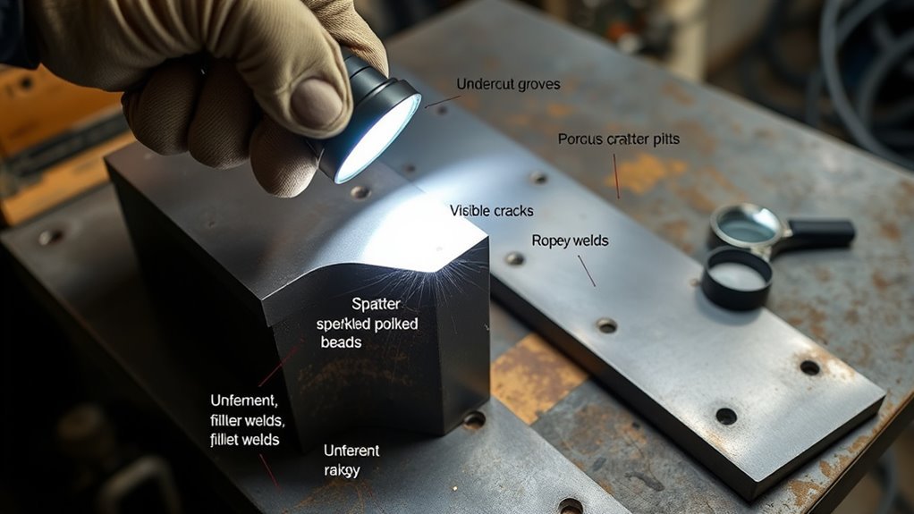
The first step in weld troubleshooting is careful visual inspection. Look for porosity, cracks, undercut, overlap, excessive spatter, burn-through, incomplete filling, irregular bead shape, visible lack of fusion, or other changes from the expected weld profile.
Do not immediately turn a knob simply because the bead looks wrong. First note where the problem appears, when it started, whether it repeats, and what changed immediately before it appeared. A new gas cylinder, wire spool, electrode batch, liner, contact tip, base material, extension cord, joint design, or operator technique can provide an important clue.
Record the process, material, thickness, filler or electrode, polarity, voltage, amperage or wire-feed setting, shielding gas, approximate travel speed, and position when troubleshooting repeated production problems. This makes it easier to separate a one-time mistake from a repeatable setup problem.
Note: Visual inspection is primarily a surface examination. A weld can look acceptable while still containing embedded lack of fusion, incomplete penetration, inclusions, or other internal discontinuities. Critical welds may require ultrasonic, radiographic, magnetic-particle, penetrant, or another inspection method specified by the applicable code or procedure.
Match the Weld Symptom to the Likely Cause
| Symptom | Common Causes | Check First |
| Porosity | Poor shielding, drafts, leaks, dirty or damp material, excessive stickout, contaminated filler | Gas supply, nozzle/cup, leaks, wind, surface cleanliness |
| Lack of fusion | Arc placed incorrectly, unsuitable angle, excessive travel speed, low heat input, restricted joint access | Technique, joint preparation, recommended parameters |
| Incomplete penetration | Poor joint preparation, insufficient root opening, low current/heat, improper technique | Joint design and root access before changing settings |
| Undercut | Excessive voltage/current, fast travel, poor angle, inadequate pause at weld toes | Travel speed, angle, parameter chart |
| Burn-through | Excessive heat, slow travel, excessive root gap, thin material | Heat setting, travel speed, fit-up |
| Excessive spatter | Wrong voltage/wire-feed relationship, polarity error, dirty metal, excessive stickout, poor shielding | Polarity, setup chart, stickout, cleanliness |
| Ropy or convex bead | Cold parameters, excessive travel speed, unsuitable technique | Voltage/current or wire feed and travel speed |
| Cracking | Joint restraint, unsuitable filler, hydrogen/moisture, crater shape, metallurgy, excessive stress | Stop and determine the crack mechanism before repair |
| Slag inclusion | Poor interpass cleaning, bead shape that traps slag, unsuitable angle or technique | Clean between passes and review bead placement |
Fix Missing or Weak Welds
A missing, undersized, visibly weak, or poorly tied-in weld can result from operator placement error, unsuitable joint preparation, insufficient heat input, poor grounding, unstable power delivery, contamination, or incorrect parameters. The correct fix depends on which variable actually caused the problem.
Start with placement. Verify the torch, gun, or electrode work angle and travel angle, and make sure the arc reaches the intended joint surfaces. On groove welds, confirm that the joint preparation gives the arc physical access to the root and sidewalls. Simply increasing amperage cannot compensate for a joint that is inaccessible.
Next, check the work connection and cables. Attach the work clamp to clean metal as close to the work area as practical, inspect cables and connectors for looseness or damage, and verify the machine is connected to a suitable power supply. Intermittent electrical contact can create an unstable arc and inconsistent weld quality.
Then confirm the machine setup against the welder’s chart, filler-metal information, or approved WPS. Make controlled changes rather than changing voltage, wire feed, travel speed, and gas flow simultaneously. One-variable-at-a-time adjustments make the result much easier to interpret.
After correcting the suspected cause, make a test weld on comparable material when practical and inspect it before continuing production.
Fix Porosity, Fusion, and Bead Shape Issues
Porosity
Weld porosity occurs when gas becomes trapped in solidifying weld metal. Common causes include inadequate shielding, gas leaks, drafts, a clogged nozzle, excessive torch-to-work distance or wire stickout, dirty base metal, moisture, contaminated filler material, and unsuitable gun or torch angle.
Do not automatically increase the regulator because porosity appears. First confirm that gas is actually reaching the weld zone, inspect hoses and fittings for leaks, clean the nozzle or cup, remove spatter, block strong drafts, and clean the joint. Both insufficient shielding and excessive turbulent gas flow can create problems.
Weld porosity usually points to a shielding or contamination problem, so check the entire gas path and joint condition before changing several machine settings.
Lack of Fusion
Lack of fusion means the weld metal has not fused completely with the base metal or a previous weld bead. It may result from insufficient heat input, incorrect arc placement, unsuitable gun or electrode angle, excessive travel speed, poor joint access, mill scale or other contamination, or parameters that are too cold for the application.
Keep the arc where fusion is required instead of allowing it to ride on top of the existing weld pool. Check joint preparation and technique before increasing heat. For MIG welding, voltage and wire-feed speed work together, so use the manufacturer’s recommended combination rather than adjusting one value far outside its normal range.
Irregular Bead Shape
A high, rope-like or excessively convex bead often indicates a cold setup, excessive travel speed, or poor tie-in. A very flat or excessively wide bead can indicate too much heat, slow travel, or excessive voltage depending on the process. Undercut can appear when the arc washes metal away from the weld toe without filling it properly.
Travel speed, arc length or contact-tip-to-work distance, work angle, and parameter balance should all be checked. The correct push, drag, or neutral technique depends on the welding process, filler, material, and position; it is not interchangeable in every application.
Troubleshoot Other Common Weld Defects
Undercut
Undercut is a groove along the weld toe that is not properly filled with weld metal. Possible causes include excessive current or voltage, fast travel, improper electrode manipulation, or an unsuitable work angle. Reduce the excessive variable, keep the arc positioned correctly, and use an appropriate pause at the toes when the process and procedure call for it.
Burn-Through
Burn-through is especially common on thin material and open-root joints when heat input is too high for the fit-up. Check voltage or current, wire feed where applicable, travel speed, root opening, and material thickness. Reducing heat, increasing travel speed within an acceptable range, or improving fit-up can help, but the exact correction depends on the process.
Excessive Spatter
Excessive spatter can come from dirty material, incorrect polarity, unsuitable voltage or wire-feed balance, excessive stickout, contaminated wire, poor shielding, or an unstable arc. Confirm polarity and consumable requirements first, especially after changing from solid wire to flux-cored wire or changing welding processes.
Slag Inclusion
Slag inclusions are mainly associated with processes that produce slag, including stick welding and many flux-cored applications. Remove slag completely between passes, avoid bead shapes that form deep pockets, maintain suitable travel and work angles, and ensure each pass adequately fuses into adjacent material.
Overlap and Cold Lap
Overlap occurs when weld metal rolls onto the base material without adequate fusion. Excessively slow travel, incorrect technique, or unsuitable parameters may contribute. Keep the arc at the appropriate leading area of the puddle and correct the parameter/technique combination instead of simply adding more weld metal.
Cracks and Crater Cracks
Cracks deserve more caution than ordinary appearance problems. They can result from hydrogen, moisture, unsuitable filler material, metallurgical sensitivity, restraint, shrinkage stress, poor joint design, or an unfilled crater. Do not simply weld over a crack. For a repair, determine its full extent and use the repair procedure required for the material and application.
Warning: A visible crack in a structural, pressure-retaining, lifting, vehicle-safety, or otherwise critical weld should be treated as an inspection and repair issue, not merely a cosmetic defect. Follow the governing code, engineering requirements, and approved repair procedure.
Check Weld Settings, Wire Feed, and Gas Coverage
Verify that machine settings match the process, filler metal, material thickness, joint design, welding position, and shielding gas before welding begins.
Start With the Recommended Parameter Chart
For MIG welding, avoid treating one wire-feed-speed range as correct for all jobs. Wire diameter and type strongly affect the relationship between wire-feed speed and amperage. Material thickness, transfer mode, shielding gas, and joint design also change the required setup.
Use the machine’s setup chart, digital parameter recommendation, filler-wire data, or approved WPS as the starting point. Fine-tune only after observing the arc and test bead.
Check Voltage and Wire Feed Together
On conventional MIG equipment, wire-feed speed strongly influences welding current, while voltage affects arc length and bead characteristics. Too little voltage can create poor arc behavior, excess spatter, and a convex bead. Excessive voltage can produce poor arc control and an unstable or overly wide bead.
Do not compensate for an extreme wire-feed setting with an extreme voltage setting. Return to a known recommended starting point if several adjustments have made the arc worse.
Set Shielding Gas for the Actual Process
There is no single correct shielding-gas flow rate for every MIG or TIG setup. Required flow changes with process, gas, torch or nozzle size, joint geometry, drafts, equipment, and manufacturer recommendations.
Set the regulator or flowmeter according to the equipment, consumable, or WPS guidance. If coverage is poor, verify the cylinder valve, regulator, gas hose, gun or torch connection, nozzle or cup, and actual flow at the torch where appropriate. Do not assume that increasing flow always improves shielding; excessive flow can create turbulence and pull surrounding air into the shielding envelope.
Pro Tip: If a weld was good and suddenly develops porosity, ask what changed before adjusting the machine. A draft, empty cylinder, loose gas fitting, damaged hose, clogged nozzle, contaminated workpiece, new wire spool, or changed stickout can create a defect even when the voltage and wire-feed settings have not moved.
Troubleshoot MIG Wire-Feed Problems
Some apparent weld defects begin before the wire reaches the arc. If wire delivery is erratic, inspect the complete feed path from spool to contact tip.
- Birdnesting: Check liner condition, drive-roll pressure, spool brake tension, gun-cable bends, and whether the drive-roll groove matches the wire.
- Burnback: Check contact-tip condition, tip-to-work distance, wire-feed stability, and the voltage/wire-feed relationship.
- Wire slipping: Inspect the drive-roll groove and pressure. Excessive pressure can deform some wires, while insufficient pressure can cause slipping.
- Erratic arc: Look for a worn or oversized contact tip, damaged liner, poor work connection, loose power connection, or contaminated wire.
- Repeated tip problems: Confirm that the contact-tip size matches the wire diameter and replace badly worn consumables.
Keep the gun cable as straight as practical during diagnosis. Tight bends increase feeding resistance and can make a liner or drive-roll problem appear worse.
Check Work Connection, Polarity, and Power Delivery
An unstable arc is not always a parameter problem. Inspect the work lead, work clamp, electrode holder or gun connections, and power-source connections before assuming the welder is incorrectly calibrated.
Attach the work clamp to clean conductive metal. Paint, rust, scale, loose clamps, damaged cable strands, or overheated connectors can increase electrical resistance and make the arc inconsistent.
Also confirm polarity whenever wire, electrode, or process changes. Solid-wire MIG, self-shielded flux-cored wire, gas-shielded flux-cored wire, stick electrodes, and TIG applications do not all use the same polarity. Follow the filler-metal and machine instructions.
Stable weld quality depends on more than machine settings. Poor electrical connections, incorrect polarity, damaged cables, or an unstable wire path can create symptoms that look like a heat-setting problem.
Prevent Repeat Weld Defects With Better Setup
Repeat weld defects become less likely when setup is controlled before the arc starts. Clean the joint and surrounding weld area as required for the material and process, verify joint fit-up, identify the correct filler or electrode, and confirm the specified polarity and machine parameters.
Inspect the power supply and work connection for stable output. Check cables, gas lines, contact tips, nozzles, liners, drive rolls, electrode condition, and other consumables as appropriate to the process. Replace worn or damaged parts instead of trying to compensate for them with machine settings.
For gas-shielded processes, confirm adequate shielding without relying on a universal CFH number. Protect the arc from drafts, keep the nozzle or cup clean, and maintain the torch-to-work distance recommended for the application.
Technique matters as much as setup. Maintain appropriate travel speed, arc position, angle, stickout, and arc length. Watch the weld puddle rather than relying only on the sound of the arc.
Change One Variable at a Time
- Identify and photograph or document the defect.
- Return the machine to a known recommended starting setup if the settings are uncertain.
- Check material preparation, joint fit-up, polarity, work connection, consumables, shielding, and wire or electrode delivery.
- Change the single variable most likely to cause the observed symptom.
- Make a short test weld on representative material when possible.
- Inspect the result and record whether the change helped.
- Continue only when the weld meets the applicable workmanship or acceptance requirements.
This method is slower than randomly adjusting several controls at once, but it identifies the actual cause and makes future troubleshooting much faster.
Know When Visual Inspection Is Not Enough
Visual inspection can reveal surface cracks, undercut, visible porosity, overlap, excessive reinforcement, underfill, misalignment, and many bead-shape problems. It cannot reliably prove that a weld is free from buried lack of fusion, internal porosity, slag inclusions, or other subsurface discontinuities.
For production or code-regulated work, acceptance should be based on the applicable drawing, WPS, contract, welding code, and inspection plan. Depending on the job, additional inspection may include magnetic-particle testing, liquid-penetrant testing, ultrasonic testing, or radiography.
If you cannot determine why a critical weld is cracking, repeatedly failing inspection, or producing internal discontinuities, stop repeating the weld and involve the appropriate welding supervisor, inspector, engineer, or other qualified professional.
Frequently Asked Questions
What Are the 12 Weld Defects?
There is no single universal standard stating that exactly 12 weld defects exist. A practical list of 12 commonly discussed weld defects or discontinuities includes cracks, porosity, lack of fusion, incomplete penetration, undercut, overlap, slag inclusion, burn-through, underfill, excessive reinforcement or convexity, crater defects, and excessive spatter. Which imperfections are acceptable depends on the welding code, specification, material, joint, and service.
Why Do Welders Drink Milk After Welding?
Drinking milk before or after welding is an old shop tradition, especially around galvanized steel, but milk is not a detoxifier and does not prevent metal fume fever or protect the lungs from welding fumes. Welding-fume exposure should be controlled with proper process selection, ventilation or local exhaust, safe work practices, and appropriate respiratory protection when required. Anyone who develops breathing difficulty, chest symptoms, fever, or significant illness after welding-fume exposure should seek appropriate medical advice rather than relying on milk.
How Can I Diagnose Problems With My MIG Welding?
Start with the machine’s recommended settings for the wire type, wire diameter, material, thickness, gas, and joint. Then check polarity, work-clamp contact, surface cleanliness, gas supply, drafts, stickout, gun angle, travel speed, contact tip, nozzle, liner, drive rolls, and wire condition. Change one variable at a time and make a test weld so you can see which correction actually improves the bead.
How to Identify a Bad Weld?
A visibly poor weld may show cracks, surface porosity, undercut, overlap, excessive spatter, burn-through, irregular bead width, poor toe blending, excessive convexity, underfill, or other discontinuities outside the applicable acceptance criteria. However, appearance alone cannot confirm internal soundness. Structural and code-regulated welds should be evaluated using the inspection method and acceptance criteria specified for that job.
Conclusion
Effective weld troubleshooting begins with accurate defect identification, but the visible defect is only the starting clue. Porosity may involve shielding, contamination, leaks, drafts, or technique. Lack of fusion may involve joint access, arc placement, travel speed, heat input, or surface condition. Unstable MIG welding may originate in the liner, contact tip, drive rolls, work connection, polarity, or power path rather than the front-panel settings.
Use manufacturer guidance or the approved WPS as the starting point, change one variable at a time, and verify the result with a test weld and the inspection method required for the job. For structural or otherwise safety-critical work, a visually improved bead is not automatically an acceptable weld; applicable acceptance criteria and, when required, qualified nondestructive testing determine whether the repair is suitable for service.
Sources
- OSHA — Welding, Cutting, and Brazing: Hazards and Solutions. Supports welding-fume, UV, electrical, burn, PPE, and other occupational-safety guidance.
- OSHA — General Requirements for Welding, Cutting, and Brazing. Supports ventilation, PPE, confined-space, and fire-prevention precautions.
- CDC/NIOSH — Welding Fumes and Manganese. Supports welding-fume exposure and inhalation-risk information.
- Miller Electric — Tips for Troubleshooting Common MIG Weld Defects. Supports porosity, lack-of-fusion, burn-through, spatter, and bead-profile troubleshooting.
- Miller Electric — MIG Welding: Setting the Correct Parameters. Supports process-specific voltage, wire-feed, travel-speed, and shielding guidance.
- American Society for Nondestructive Testing — Visual Testing. Supports the capabilities and limitations of visual inspection and the need for other NDT methods for subsurface discontinuities.