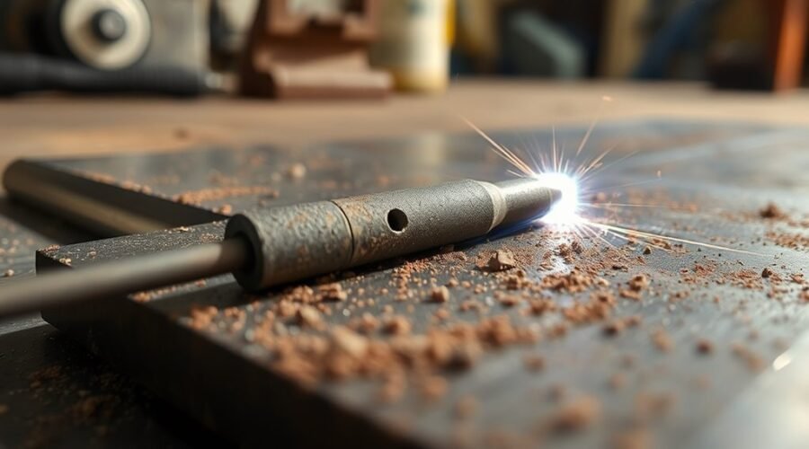
Welding porosity happens when gas becomes trapped in the weld metal as the molten pool solidifies. The most common causes are dirty or damp material, contaminated filler or electrodes, poor shielding gas coverage, gas-system leaks, drafts, excessive gas flow, incorrect technique, and unsuitable welding parameters. The best fix is to identify the gas source first, correct it, and repair unacceptable porous metal according to the applicable welding procedure.
Quick Answer
Welding porosity is caused by gas becoming trapped as weld metal freezes. Start by checking cleanliness, moisture, shielding gas, leaks, drafts, nozzle condition, consumables, torch or gun position, and welding parameters. If the porosity exceeds the applicable acceptance criteria, remove the defective metal, correct the root cause, and re-weld using the approved procedure.
Key Takeaways
- Welding porosity consists of gas cavities trapped in solidified weld metal.
- Oil, grease, rust, oxide, paint, moisture, dirty filler, and damp electrodes or flux can generate gas in the weld pool.
- Both too little shielding gas and excessively high gas flow can cause porosity; excessive flow may create turbulence and pull air into the shield.
- Shielding-gas settings are process- and equipment-dependent. Follow the WPS, machine chart, consumable guidance, or manufacturer instructions rather than one universal CFH value.
- Not every pore automatically means a weld must be rejected. Acceptance depends on the governing code, specification, service, size, amount, and distribution of porosity.
- When repair is required, remove defective metal to sound material, correct the cause, and re-weld under the approved procedure.
At a Glance
| Time Required | About 10–30 minutes for basic troubleshooting; repair and inspection may take longer |
| Difficulty | Beginner to intermediate for troubleshooting; code-governed repair may require a qualified welder and approved WPS |
| Tools Needed | PPE, clean brush or grinder, approved cleaner, clean rags, flowmeter/regulator, leak-test solution, and inspection tools appropriate to the job |
| Cost | Usually low for cleaning and basic troubleshooting; professional NDT or structural repair can cost considerably more |
What Is Welding Porosity?
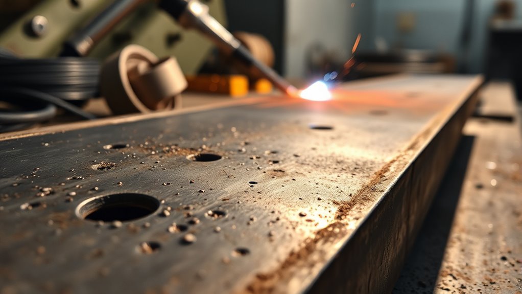
Welding porosity is the presence of cavities in weld metal caused by gas that becomes trapped while the molten weld pool solidifies. TWI identifies several forms, including distributed pores, surface-breaking pores, wormholes, and crater-related cavities.
Porosity forms when gases in the molten weld pool cannot escape before the metal solidifies.
Gas can enter or form in the weld pool through poor atmospheric shielding, surface contamination, moisture, contaminated consumables, coatings, gas-line problems, or unstable welding conditions.
Porosity may be visible as small pinholes at the surface or may remain below the surface and require inspection to detect. Its importance depends on the number, size, shape, location, and distribution of the pores as well as the service requirements of the welded component.
Note: Porosity is not automatically rejectable simply because a pore exists. Structural, pressure-containing, fatigue-sensitive, leak-critical, and code-governed welds must be evaluated against the acceptance criteria specified by the applicable code, drawing, contract, or welding procedure.
Common Types of Weld Porosity
| Type | What It Looks Like | Common Clue |
|---|---|---|
| Distributed porosity | Many small pores spread through the weld | Air entrainment, contamination, or shielding problems |
| Surface-breaking pores | Visible pinholes or cavities at the weld surface | Often accompanies more extensive internal porosity |
| Wormholes | Elongated gas cavities | Heavy contamination, coatings, or gas generated in a crevice |
| Crater pipe or crater cavity | Cavity near the end of a weld | Poor crater filling or abrupt arc termination |
What Causes Welding Porosity?
The main causes of welding porosity are contamination, moisture, inadequate or turbulent shielding, leaking gas equipment, drafts, unsuitable consumables, and unstable welding technique or parameters.
According to TWI, nitrogen and oxygen absorption commonly results from poor shielding, while hydrogen may come from moisture, grease, oil, damp electrodes, fluxes, or workpiece surfaces.
| Likely Cause | Typical Clue | First Check |
|---|---|---|
| Oil, grease, rust, oxide, paint, or dirt | Porosity follows dirty areas or occurs irregularly | Clean joint and adjacent surfaces correctly |
| Moisture or condensation | Problem appears after cold storage, damp weather, or wet consumables | Dry material and consumables according to procedure |
| Low shielding-gas flow | Oxidation or porous bead with poor coverage | Check actual flow, cylinder, regulator, hoses, and nozzle |
| Excessive shielding-gas flow | Porosity persists even after increasing CFH | Reduce flow to the lowest effective rate specified for the setup |
| Drafts | Problem changes with doors, fans, wind, or torch orientation | Block disruptive airflow without compromising required ventilation |
| Gas leak or restriction | Flowmeter setting looks correct but shielding remains poor | Leak-test and inspect the complete gas path |
| Excessive gun/torch angle or long arc | Coverage becomes inconsistent as technique changes | Return to the process-specific recommended angle and arc length |
Contamination in Joint Area
Oil, grease, dirt, rust, oxide, paint, heavy mill scale, cutting-fluid residue, and some coatings can release gases or interfere with weld-pool protection. Their effect varies by material and process.
| Contaminant | Possible Effect |
|---|---|
| Oil and grease | Hydrocarbon contamination and gas generation |
| Rust and oxide | Unstable welding conditions and contamination |
| Heavy mill scale | May interfere with fusion or weld-pool cleanliness depending on process |
| Moisture | Potential hydrogen source |
| Paint or primer | Gas/fume generation and possible porosity if not permitted by the procedure |
Clean the joint and the nearby area using the method appropriate to the alloy and welding procedure. Degreasing should normally be done before mechanical oxide removal and before final fit-up when trapped cleaner would be difficult to remove.
Warning: Do not use chlorinated solvent vapors around an exposed welding arc. OSHA warns that chlorinated-hydrocarbon cleaning vapors must be kept out of the welding atmosphere because hazardous decomposition products can form. Follow the cleaner manufacturer’s safety instructions and make sure cleaned surfaces are completely dry before welding.
Galvanized, painted, plated, or otherwise coated metals also require appropriate fume controls. Do not treat coating removal only as a porosity issue; the coating itself may create hazardous welding fumes.
Shielding Gas Problems
Poor shielding is one of the most common causes of porosity in MIG and TIG welding. Problems may include low flow, excessive flow, a nearly empty cylinder, wrong gas, leaks, restricted hoses, dirty nozzles, missing torch components, excessive nozzle-to-work distance, or environmental airflow.
More gas is not automatically better. Excessive flow can become turbulent and draw surrounding air into the shielding envelope. Miller’s TIG guidance specifically notes that TIG flows commonly vary from about 10 to 35 CFH and should be matched to consumables and surrounding conditions.
For one common mild-steel MIG setup, Miller recommends about 20–25 CFH. That should not be treated as a universal number for every MIG application. Nozzle size, shielding gas, transfer mode, wire type, joint, position, and environment all matter.
TWI reports that even small amounts of air entrainment in shielding gas can produce porosity, which is why leak control, stable flow, and draft protection matter.
Improper Welding Parameters
Welding parameters can influence porosity when they create excessive turbulence, an unstable arc, poor transfer, inadequate fusion, or a weld pool that solidifies before gas can escape.
Voltage, amperage, wire-feed speed, travel speed, arc length, electrode extension, polarity, and heat input must match the process, filler, material thickness, joint, and position. Avoid treating one setting as correct for every application.
For GMAW, excessively long electrode extension, excessive travel angle, unstable wire feeding, and unsuitable voltage or wire-feed speed can degrade gas coverage or arc stability. For GTAW, an unnecessarily long arc, contaminated tungsten, incorrect cup setup, poor pre-flow/post-flow, or excessive tungsten extension can contribute to contamination.
If the weld was previously sound and porosity suddenly appears, first check what changed: gas cylinder, consumables, material batch, weather, cleaner, torch setup, nozzle, wire, electrode storage, or machine settings.
Clean Base Metal Before You Weld
Thorough cleaning is one of the most reliable ways to prevent welding porosity. Remove the contaminants that the selected process and procedure cannot tolerate before striking the arc.
- Remove oil and grease with an approved cleaner suitable for the material.
- Allow the cleaner to evaporate completely before welding.
- Remove rust, loose scale, oxide, paint, or other prohibited coatings using the correct mechanical or chemical method.
- Use material-specific tools where cross-contamination matters, such as dedicated stainless-steel brushes for aluminum or stainless work.
- Keep cleaned joint faces from being recontaminated by dirty gloves, benches, clamps, or grinding debris.
- Inspect the joint immediately before welding, especially after long delays between cleaning and welding.
Aluminum deserves special attention because moisture and hydrocarbons can supply hydrogen to the weld pool. Stainless steels and other alloys also have material-specific contamination concerns, so use the cleaning method stated by the procedure or filler/material manufacturer.
Pro Tip: When chasing intermittent porosity, weld a short test coupon made from freshly cleaned material with known-good consumables. If the coupon is clean, compare its setup with the problem joint one variable at a time instead of changing several settings at once.
Stop Contamination From Consumables
Clean base metal will not prevent porosity if the filler wire, filler rod, electrode, flux, or gas-delivery system introduces contamination.
Store electrodes, filler rods, wires, and fluxes according to their manufacturer’s requirements. Moisture-sensitive products may require controlled storage or redrying procedures, while some consumables should be discarded once contaminated.
- Keep filler wire and rods clean, dry, and protected from shop dirt.
- Do not handle cleaned filler unnecessarily with bare, oily hands.
- Inspect exposed wire for rust, dirt, lubricant, or other contamination.
- Follow manufacturer instructions for storing and conditioning low-hydrogen electrodes and flux.
- Keep different filler alloys separated and clearly labeled.
- Replace damaged or questionable consumables instead of trying to weld through contamination.
Consumable control is especially important when porosity begins after changing wire spools, electrode batches, filler rods, flux, or storage conditions.
Fix Shielding Gas Flow Problems
Shielding gas must reach the weld pool at the correct flow and without contamination. A flowmeter reading alone does not prove that the weld is receiving proper coverage.
- Confirm the correct gas. Make sure the cylinder contains the gas or mixture required by the WPS or process.
- Check cylinder supply. A depleted cylinder or regulator problem can interrupt shielding.
- Set flow to the specified range. Use the WPS, equipment chart, torch/nozzle guidance, or manufacturer recommendation.
- Do not keep increasing CFH blindly. Excess flow may create turbulence and entrain air.
- Inspect hoses and fittings. Look for cuts, loose fittings, cracked seals, kinks, and restrictions.
- Check the gun or torch. Clean spatter from the MIG nozzle and confirm TIG torch components, insulators, collets, gas lens/collet body, and cup are installed correctly.
- Verify nozzle-to-work distance. Excessive distance can allow shielding to disperse before reaching the weld pool.
- Check pre-flow and post-flow where applicable. TIG welding needs adequate shielding before arc initiation and while the hot weld/tungsten cools.
If possible, verify actual flow at or near the torch rather than assuming the regulator setting equals the delivered flow.
Prevent Drafts and Moisture
Drafts can displace shielding gas, while moisture can supply hydrogen or contaminate the weld zone. Control both without creating an unsafe work environment.
Stop Air Drafts
Open doors, fans, outdoor wind, air-conditioning outlets, and crossflow from ventilation systems can disturb shielding gas around a MIG or TIG weld.
- Shield the weld zone with suitable welding screens or barriers.
- Reposition fans or air outlets that blow directly across the arc.
- Keep outdoor gas-shielded welding protected from wind.
- Maintain required fume extraction and general ventilation; do not eliminate worker-protection ventilation merely to preserve shielding gas.
- If airflow cannot be adequately controlled, use a welding process and procedure suitable for those field conditions.
There is no single draft-speed number that applies to every gas, nozzle, process, joint, and welding position. Judge airflow against the qualified procedure and whether it is disturbing the shielding envelope.
Control Moisture Exposure
Condensation can form when cold metal, electrodes, wire, or equipment is brought into a warmer humid environment. Moisture may then contribute hydrogen to the weld pool.
Base metal and consumables should be dry before welding. If drying or preheating is needed, follow the applicable material specification, consumable instructions, or WPS rather than using one generic temperature for every job.
Also inspect storage areas and gas lines for moisture. Aluminum filler wire, fluxes, and moisture-sensitive electrodes deserve particular attention.
Check Equipment and Gas Leaks
A gas system can leak or become restricted anywhere between the cylinder and the nozzle. When porosity appears unexpectedly, inspect the complete gas path.
- Confirm the gas cylinder is open and contains the correct shielding gas.
- Inspect the regulator and flowmeter for damage or erratic readings.
- Check hose connections, O-rings, seals, and quick-connect fittings.
- Use an approved leak-detection solution where appropriate; never use an open flame to check for a gas leak.
- Inspect hoses for cracking, burns, kinks, pinching, or abrasion.
- Check the gun or torch gas passages for restrictions.
- Remove MIG nozzle spatter that interferes with gas distribution.
- Verify TIG torch insulators and gas-delivery components are fitted correctly.
A useful test is to pressurize the system according to manufacturer instructions and look for unexpected pressure loss. Follow the equipment manual for the correct leak-check procedure.
Improve Torch Angle and Arc Control
Torch or gun position affects both arc behavior and shielding coverage. The correct angle depends on the welding process, joint type, position, material, and transfer mode.
For many MIG welds, a modest travel angle is appropriate. Miller describes approximately 5–15 degrees as a normal MIG travel-angle range and warns that excessive angles can increase spatter and arc instability. Work angle must still match the joint.
Do not apply the same technique to every process. Self-shielded FCAW commonly uses a drag technique, while aluminum MIG generally favors a push technique. TIG torch and filler positioning also differ from MIG gun positioning.
Keep the arc stable and avoid an unnecessarily long arc. Correct arc length is process- and setup-dependent; follow the procedure or equipment guidance rather than treating a single fraction-of-an-inch dimension as universal.
For MIG, also control electrode extension or stickout. For TIG, keep the cup, tungsten extension, gas lens or collet body, and torch angle consistent with the required shielding coverage.
Porosity Troubleshooting by Welding Process
| Process | Common Porosity Checks |
|---|---|
| MIG / GMAW | Dirty base metal, wrong/low/excessive gas flow, drafts, nozzle spatter, gas leaks, excessive gun angle, excessive stickout, damaged liner or erratic wire feed, contaminated wire, incorrect parameters |
| TIG / GTAW | Contaminated base metal or filler, contaminated tungsten, inadequate/excessive flow, poor torch assembly, wrong cup size, missing/damaged insulator, long arc, drafts, insufficient pre-flow/post-flow |
| Stick / SMAW | Damp or damaged electrodes, contaminated joint, excessive arc length, unsuitable current, incorrect electrode storage, poor technique |
| FCAW | Contamination, moisture, incorrect polarity or parameters, excessive stickout, poor travel angle, and shielding-gas problems for gas-shielded FCAW |
| SAW | Damp flux, contaminated joint surfaces, inadequate flux coverage, contaminated recovered flux, and procedure-related gas entrapment |
A Fast Welding Porosity Troubleshooting Sequence
- Stop and inspect the defect. Determine whether it is isolated, clustered, widespread, surface-breaking, or concentrated at starts/stops.
- Check the joint. Look for oil, grease, moisture, coatings, rust, oxide, cutting fluid, or trapped contamination.
- Check the filler or electrode. Confirm it is clean, dry, correctly stored, and correct for the job.
- Check shielding. Verify the correct gas, cylinder supply, flow, hoses, fittings, nozzle/cup, torch components, and environmental airflow.
- Check technique. Correct excessive arc length, torch/gun angle, stickout, travel speed, and inconsistent movement.
- Check parameters. Compare voltage, current, wire-feed speed, polarity, and other settings with the WPS or machine chart.
- Run a test coupon. Use cleaned material and known-good consumables before reworking an important component.
- Inspect the result. If the test weld is clean, transfer the corrected setup to the production joint.
How Is Weld Porosity Detected?
Surface porosity may be visible during visual inspection, but subsurface porosity can require nondestructive examination.
- Visual testing (VT): identifies visible surface pores and overall weld condition.
- Liquid penetrant testing (PT): can reveal surface-breaking discontinuities on suitable nonporous materials.
- Magnetic particle testing (MT): can find surface and near-surface discontinuities in suitable ferromagnetic materials.
- Radiographic testing (RT): is often effective for detecting and characterizing volumetric porosity.
- Ultrasonic testing (UT): can detect subsurface imperfections, although technique and sensitivity depend on geometry, material, defect size, and procedure.
TWI notes that radiography is normally more effective for characterizing porosity, while the actual inspection method and acceptance criteria must follow the governing specification.
How to Fix Weld Porosity and Prevent Rework
Do not automatically weld over visible porosity. First determine whether the discontinuity is acceptable under the applicable specification. If repair is required, identify the cause before depositing more weld metal.
- Confirm repair is required. Compare the indication with the governing drawing, code, specification, or acceptance standard.
- Identify the root cause. Check contamination, moisture, shielding gas, leaks, consumables, technique, and parameters.
- Remove unacceptable porous metal. Grinding, machining, or approved gouging may be used to reach sound metal.
- Inspect the excavation when required. Make sure the unacceptable porosity has been removed before rebuilding the joint.
- Clean the repair area. Remove grinding residue, oil, moisture, and other contamination.
- Restore correct welding conditions. Use the proper gas, consumables, settings, torch/gun setup, and environmental controls.
- Re-weld using the approved procedure. Structural or code-governed repairs should follow the applicable WPS and qualification requirements.
- Perform required final inspection. Use the examination method and acceptance criteria specified for the component.
TWI states that localized porosity repairs commonly require gouging or grinding and that widespread porosity may require removal of the entire weld before the joint is prepared and welded again.
Warning: Do not improvise repairs on pressure vessels, load-bearing structures, lifting equipment, pipelines, critical automotive components, or other safety-critical weldments. Follow the governing code, engineering requirements, qualified welding procedure, and inspection requirements.
Frequently Asked Questions
Why Do Welders Drink Milk After Welding?
Drinking milk after welding is an old workplace tradition, but milk is not an antidote or proven method for removing welding fumes from the body. The important protections are controlling fume at the source, using suitable ventilation and respiratory protection when required, and following occupational-safety procedures. If someone develops significant breathing difficulty, chest symptoms, or other concerning symptoms after fume exposure, they should leave the exposure area and seek appropriate medical evaluation.
What Are the Main Causes of Porosity in Welds?
The most common causes are contaminated base metal or filler, moisture, poor or turbulent shielding gas coverage, leaks, drafts, incorrect gas, dirty nozzles or torch components, excessive arc length or gun angle, unsuitable consumable storage, and welding parameters that destabilize the weld pool.
How Do You Fix Porosity in Welds?
First identify and correct the cause. If the porosity is unacceptable under the applicable inspection criteria, remove the defective area to sound metal by an approved method, clean and prepare the excavation, then re-weld using the correct procedure. Required inspection should be performed after repair.
Can You Weld Over Porosity?
Do not simply cover unacceptable porosity with another weld pass. Doing so can leave the original gas cavities trapped underneath the repair. Evaluate the weld against the governing acceptance criteria and, when repair is required, remove defective material to sound metal before re-welding.
Can Too Much Shielding Gas Cause Porosity?
Yes. Excessive shielding-gas flow can become turbulent and pull surrounding air into the gas stream. Use the lowest effective flow that provides complete shielding and stays within the range specified by the WPS or equipment and consumable manufacturer.
Is Porosity Always a Weld Failure?
No. Whether porosity is acceptable depends on its size, quantity, distribution, location, weld type, service conditions, and the code or specification governing the work. Never use appearance alone to accept or reject a safety-critical weld.
Sources
- TWI — Porosity in Welding — definition, causes, prevention, types, detection, and remedial action.
- Miller Electric — Understanding the Basics of MIG Welding for Mild Steel — MIG gas flow, cleanliness, stickout, and gun-angle guidance.
- Miller Electric — Best Practices for Proper Shielding Gas in TIG Welding — TIG flow, turbulence, cup selection, pre-flow, and post-flow.
- OSHA — 29 CFR 1910.252 Welding, Cutting, and Brazing — welding safety, ventilation, and cleaning-compound precautions.
- NIOSH/CDC — Welding Fumes and Manganese — occupational welding-fume exposure and health guidance.
Conclusion
Welding porosity is usually preventable once the source of gas contamination is identified. Start with clean, dry material and consumables, then verify shielding gas, gas-system integrity, airflow, torch or gun setup, and welding parameters. Avoid universal settings that ignore the process or WPS. When porosity is unacceptable, remove the affected metal to sound material, correct the cause, and re-weld using the approved procedure. Careful troubleshooting before repair reduces repeat defects, wasted consumables, and unnecessary rework.