MIG welding aluminum is different from welding mild steel because aluminum conducts heat quickly, develops a stubborn oxide layer, and uses soft filler wire that is harder to feed. A compatible spool gun or push-pull system, clean aluminum, pure argon, correct filler wire, and machine-specific settings make the process much more predictable.
Quick Answer
To MIG weld aluminum, use a welder configured for aluminum with a compatible spool gun or push-pull feeder, DCEP polarity, 100% argon, and suitable aluminum wire such as ER4043 or ER5356. Degrease and brush the joint, use a 10–15 degree push angle, then set voltage and wire speed from your welder’s aluminum chart.
Key Takeaways
- Use a compatible spool gun or push-pull system so soft aluminum wire feeds without birdnesting.
- Use DCEP polarity and 100% argon; 20–30 CFH is a common starting gas-flow range.
- Do not rely on one universal voltage or wire-speed setting. Start with the chart supplied for your welder, wire diameter, alloy, and material thickness.
- ER4043 works well for many 6xxx-series jobs, while ER5356 may be preferred when greater strength, stiffness, or anodized color matching is important.
- Degrease first, then remove oxide with a dedicated stainless steel brush immediately before welding.
- Use a 10–15 degree push angle, roughly 1/2–3/4 inch wire stickout, straight beads, and enough travel speed to prevent excessive heat buildup.
At a Glance
| Time Required | Varies by joint; allow extra time for cleaning, setup, and scrap test welds before the final part. |
| Difficulty | Intermediate; aluminum has a narrower working window than mild steel. |
| Tools Needed | Aluminum-capable MIG welder, compatible spool gun or push-pull system, argon cylinder and regulator/flowmeter, aluminum wire, dedicated stainless brush, residue-free cleaner, clamps, and welding PPE. |
| Cost | Depends on the equipment you already own; the main ongoing consumables are argon and filler wire, plus a spool gun or push-pull system if your welder requires one. |
Warning: MIG welding produces intense ultraviolet and infrared radiation, hot metal, sparks, electrical hazards, and fumes. Wear a welding helmet with the correct shade, flame-resistant clothing, gloves, and suitable eye protection. Keep flammables away, secure shielding-gas cylinders upright, and provide adequate ventilation or local fume extraction. Follow your welder, gas-cylinder, and workplace safety instructions.
What You Need for MIG Welding Aluminum
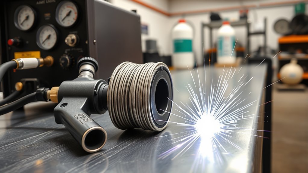
Successful MIG welding aluminum begins with equipment designed to feed soft aluminum wire consistently. A spool gun is a common solution because the wire spool sits close to the contact tip, shortening the feed path and greatly reducing the chance of birdnesting. A properly configured push-pull system is another standard option, particularly when longer gun reach or higher production output is needed.
Miller’s aluminum MIG guidance lists spool guns and push-pull systems as common feeding choices and recommends 100% argon for conventional aluminum MIG welding.
- MIG welder: The machine must have enough output for the material thickness and must support the spool gun or push-pull feeder you intend to use.
- Polarity: Conventional solid-wire aluminum GMAW uses DCEP, or direct-current electrode positive.
- Shielding gas: 100% argon is the normal choice. Argon-helium blends can be useful for some thicker sections and specialized procedures.
- Filler wire: Common choices include ER4043 and ER5356.
- Cleaning tools: Use a residue-free solvent and a stainless steel brush dedicated only to aluminum.
- PPE: Use a welding helmet, safety glasses, gloves, flame-resistant clothing, and ventilation appropriate to the job.
Note: Conventional spray-transfer aluminum MIG is generally better suited to material around 14 gauge and thicker. Aluminum thinner than about 0.074 inch may be easier to control with specialized pulsed MIG or AC TIG equipment, depending on the machine and joint.
Check Material Thickness and Welder Output
Before loading wire, confirm that the welder can produce the output required for the joint. Aluminum conducts heat rapidly, so the machine needs enough current to establish fusion before heat spreads through the workpiece.
Miller’s current aluminum MIG guide identifies approximately 14 gauge and heavier as a typical range for conventional MIG aluminum work, while noting that the practical upper limit depends on the welder’s output. Very thin aluminum may require pulsed MIG or AC TIG for better heat control.
Do not assume that a machine capable of welding a certain thickness of steel will have the same aluminum capacity. Check the manufacturer’s chart or manual for the exact wire diameter, material thickness, and gun being used.
Choose a Spool Gun and Filler Wire
A spool gun places the wire spool directly on the gun and gives the soft filler wire only a short path to the contact tip. This reduces buckling, birdnesting, and feeding resistance. Before buying or installing one, verify that the spool gun is electrically and mechanically compatible with your MIG welder.
The filler wire must match both the base-metal alloy and the finished part’s service requirements. For 6061 aluminum, both ER4043 and ER5356 are commonly used; one is not automatically best for every job.
| Filler | Typical Advantages | When It May Be Preferred |
|---|---|---|
| ER4043 | Good fluidity, smooth bead appearance, lower melting range, and good resistance to hot cracking on many common aluminum combinations. | General 6xxx-series fabrication and applications where its welding characteristics suit the procedure. |
| ER5356 | Stiffer wire, good feedability, higher as-welded strength in many applications, and a better color match after anodizing. | Jobs where strength, ductility, feedability, or anodized appearance makes it the more appropriate filler. |
The American Welding Society’s aluminum preparation guidance emphasizes matching filler metal to the base alloy and intended service rather than selecting filler by one rule alone.
Pro Tip: Keep aluminum wire dry and covered. Moving cold wire into a warm, humid shop can cause condensation, which can contribute to porosity and feeding problems.
Choose the Best Gas for MIG Welding Aluminum
100% argon is the standard shielding gas for most conventional MIG welding of aluminum. It supports a stable spray-transfer arc and protects the molten weld pool from atmospheric contamination.
- 100% argon: The normal starting choice for aluminum MIG welding.
- 20–30 CFH: A common starting flow range cited by Miller, although the correct flow depends on nozzle size, joint geometry, drafts, gun angle, and equipment.
- Argon-helium blends: Sometimes used for thicker sections when additional heat input or penetration is desirable.
- Avoid steel MIG mixes containing CO2: They are not the normal shielding gases for aluminum GMAW and can seriously degrade weld quality.
Do not increase the gas flow blindly when a weld becomes dirty. First check the cylinder, regulator or flowmeter, hose connections, gun, nozzle, drafts, and gun angle. Poor gas coverage can come from leaks or turbulence as well as insufficient flow.
For conventional aluminum MIG welding, pure argon and clean base metal are more important than chasing a single universal gas-flow number.
Dial In Aluminum MIG Settings
There is no single voltage and wire-feed-speed combination that works for every aluminum MIG job. Settings change with the welder, material thickness, wire diameter, filler alloy, joint design, transfer mode, and gun.
The best starting point is the aluminum chart inside the welder, the owner’s manual, or the spool-gun setup chart supplied by the manufacturer. Some aluminum jobs on thinner sheet run well below 20 volts, while thicker material may use settings in the 20-volt range or higher.
| Setting | Starting Guidance |
|---|---|
| Polarity | DCEP for conventional solid-wire aluminum MIG. |
| Voltage | Use the machine’s aluminum chart. Do not treat 20–24 V as a universal range. |
| Wire feed speed | Use the manufacturer’s starting value for the wire diameter and thickness, then tune for stable spray transfer without stubbing or burnback. |
| Gas flow | Approximately 20–30 CFH is a common starting range with 100% argon. |
| Wire stickout | Roughly 1/2–3/4 inch is common with spool-gun aluminum welding. |
| Contact-tip recess | About 1/8 inch inside the nozzle where the gun design allows it. |
| Travel angle | About 10–15 degrees in the push direction. |
Make test welds on scrap that matches the actual alloy and thickness. Evaluate bead shape, fusion, penetration, soot, arc stability, and heat buildup before welding the finished part.
Clean Aluminum Before You Weld
Aluminum must be clean before welding. Oil, grease, moisture, shop dirt, and the natural aluminum-oxide layer can contribute to porosity, unstable arc behavior, lack of fusion, and poor wire performance.
The order matters. Miller’s aluminum cleaning guidance recommends removing oils and other contaminants first, then mechanically removing the oxide layer.
- Degrease first. Use a residue-free cleaner suitable for aluminum.
- Dry the joint. Use clean disposable material rather than an oily shop rag.
- Remove oxide. Brush the weld area with a stainless steel brush dedicated only to aluminum.
- Use light pressure. Excessive power brushing can smear the aluminum surface and trap contamination.
- Clean close to welding time. The oxide layer begins reforming after the surface is exposed to air.
- Inspect both sides of the joint. Contaminants on the back side can also affect the weld.
Warning: Do not use chlorinated solvents in the welding area. Under arc heat and ultraviolet radiation, some chlorinated cleaners can form highly toxic decomposition products. Follow the cleaner manufacturer’s safety instructions.
Avoid aggressive general-purpose grinding when possible. If mechanical cutting or abrasion is necessary, use tools and abrasives intended for aluminum and prevent embedded abrasive or cross-contamination from steel.
Use the Right Gun Angle and Travel Speed
Use a push technique when MIG welding aluminum. Hold the gun at approximately a 10–15 degree push travel angle so the shielding gas covers the weld zone ahead of the puddle.
A drag technique can reduce shielding effectiveness and increase soot or porosity. Keep the gun position consistent and use straight stringer beads rather than large weave patterns.
Travel speed should be fast enough to stay ahead of excessive heat buildup while still producing proper fusion. As the aluminum heats during a longer weld, you may need to increase travel speed or break the weld into shorter sections.
Do not rely on a rule such as “twice the steel travel speed.” The correct travel speed is the speed that maintains the required bead profile and fusion without allowing the puddle to become excessively wide or the base metal to sag or burn through.
Set Stickout, Voltage, and Wire Feed
Stickout, voltage, and wire feed work together. Use your machine’s chart as the baseline and make small, controlled adjustments rather than changing several parameters at once.
Set Proper Stickout
With many aluminum spool-gun setups, a wire stickout of roughly 1/2–3/4 inch works well. Aluminum commonly uses more stickout than short-circuit steel MIG.
Do not confuse wire stickout with nozzle position. The contact tip may also be recessed roughly 1/8 inch inside the nozzle, depending on gun design.
If the gun is held too close, radiant heat from the aluminum puddle can contribute to wire burnback and contact-tip problems. If the wire extension is excessive, arc stability and gas coverage can suffer.
- Wire stickout: roughly 1/2–3/4 inch.
- Contact-tip recess: roughly 1/8 inch where applicable.
- Push angle: about 10–15 degrees.
- Check: stable arc, proper bead shape, and no repeated burnback.
Tune Voltage First
Begin with the voltage recommended by the welder manufacturer for the specific wire diameter and material thickness. Voltage strongly affects arc length and bead profile, but it should not be adjusted independently of wire feed speed.
A value in the 20–24 V area can appear on some charts for thicker aluminum and certain wire sizes, but it is not a minimum or universal aluminum setting. Thin aluminum may require substantially less voltage.
Make small changes while watching the arc and bead. Too little voltage can produce an unstable or stubbing arc and poor fusion. Too much can make the arc excessively long and increase heat input.
Match Wire Feed
After selecting a manufacturer-recommended starting point, match wire feed to the voltage and joint. Aluminum wire-feed speeds commonly run high, but the correct number is machine-specific.
- Start from the welder’s aluminum setting chart.
- Listen and watch for a stable spray-transfer arc rather than wire repeatedly striking the puddle.
- Increase wire feed if the wire is burning back excessively and the rest of the setup is correct.
- Reduce or rebalance wire feed and voltage if the arc is harsh, unstable, or produces an oversized bead.
- Retest on scrap after every meaningful adjustment.
Comparing wire-feed speed with an unspecified steel setting is less reliable than using the manufacturer’s aluminum chart because different machines, wire sizes, and processes use different calibrated ranges.
Can You MIG Weld Aluminum Without a Spool Gun?
Yes. A spool gun is not the only correct way to MIG weld aluminum. A push-pull gun uses a motor in the gun to pull the wire while the feeder assists from the machine, allowing reliable feeding over a longer path.
Trying to push very soft aluminum wire through a long steel-oriented MIG setup can cause birdnesting, buckling, and inconsistent feeding. Some machines can be specially configured for aluminum, but the drive rolls, liner, contact tip, wire diameter, and gun length must all be appropriate for the manufacturer’s recommended setup.
For many home and repair welders, a compatible spool gun is the simplest conversion because it keeps the wire path short.
Welding Safety Before You Start
Aluminum MIG welding has the same core arc-welding hazards as other GMAW processes. OSHA’s welding requirements address eye and face protection, protective clothing, ventilation, fire prevention, and work in confined spaces.
- Protect your eyes and skin: Use a welding helmet with the correct lens shade, safety glasses, gloves, and flame-resistant clothing.
- Control fumes: Use adequate general ventilation or local exhaust so fumes do not accumulate in the breathing zone.
- Remove coatings: Identify and safely remove paint, plating, grease, or other coatings that may create hazardous fumes when heated.
- Prevent fire: Remove combustibles from the area and keep suitable fire-control equipment nearby.
- Secure gas cylinders: Keep the argon cylinder upright and secured, protect the valve, and follow the supplier’s handling instructions.
- Avoid confined-space welding without proper procedures: Confined spaces require additional ventilation, monitoring, and rescue precautions.
For safety-critical, load-bearing, structural, pressure, or regulated fabrication, follow an approved welding procedure and the applicable code rather than relying only on general online settings.
Fix Burn-Through, Porosity, and Dirty Welds
Most aluminum MIG defects can be traced to heat input, contamination, shielding gas, wire feeding, gun technique, or incorrect machine settings.
| Problem | Likely Causes | What to Check |
|---|---|---|
| Burn-through | Too much heat, slow travel, large gap, thin material. | Increase travel speed, shorten welds, improve fit-up, spread heat around the part, or use a process with better thin-material control. |
| Porosity | Oil, moisture, hydrated oxide, drafts, gas leak, poor shielding. | Clean correctly, verify argon flow, inspect hoses/nozzle, shield the weld from drafts, and keep filler wire dry. |
| Black soot / dirty weld | Drag angle, contamination, poor gas coverage, unsuitable settings. | Use a push angle, clean the metal, verify shielding, and confirm that the machine is operating in the intended aluminum transfer range. |
| Wire burnback | Gun too close, incorrect wire/feed balance, worn or wrong contact tip. | Restore proper stickout, check the contact tip, and rebalance the machine settings. |
| Birdnesting | Soft wire buckling, excessive drive-roll tension, incorrect roll or tip, feed restriction. | Check spool-gun setup, drive-roll tension, contact-tip size, spool drag, and wire path. |
| Lack of fusion | Oxide layer, insufficient heat, poor joint preparation, excessive travel speed. | Clean the oxide properly, confirm settings, improve joint access, and verify that travel speed still allows fusion. |
Increase travel speed and use shorter welds when excessive heat is causing the aluminum to sag or burn through.
When a problem appears, change one variable at a time. That makes it easier to identify whether the cause is machine setup, cleaning, gas coverage, feeding, or technique.
Practice on Scrap Before Welding the Real Part
Before welding the finished component, test the setup on scrap aluminum that matches the real part as closely as possible in alloy, thickness, joint type, and orientation.
- Set polarity, gas, wire type, wire diameter, voltage, and wire feed from the manufacturer’s chart.
- Degrease and brush the scrap using the same preparation method planned for the real joint.
- Hold a consistent 10–15 degree push angle.
- Maintain the intended stickout and gun distance.
- Run a straight bead and watch puddle size, bead shape, fusion, soot, and heat buildup.
- Make one adjustment at a time until the arc and bead are repeatable.
If the part has several welds, remember that aluminum will progressively heat up. Settings and travel technique that work on the first cold weld may create excess heat later, so sequence the welds and allow cooling when necessary.
Frequently Asked Questions
What Is the Recommended Gas Setting for an Aluminum Spool Gun?
Use 100% argon for conventional aluminum MIG welding. A flow of roughly 20–30 CFH is a common starting range, but nozzle size, drafts, joint shape, gun angle, and the manufacturer’s instructions can change the final setting.
What Are the Recommended Settings for an Aluminum Spool Gun?
Use DCEP polarity, 100% argon, and the voltage and wire-feed values specified by the welder manufacturer for your aluminum thickness, wire alloy, and wire diameter. Many spool-gun applications use about 1/2–3/4 inch wire stickout and a 10–15 degree push angle, but voltage and wire speed are not universal.
What Is the Best Setting for MIG Welding Aluminum?
There is no single best setting. Begin with the aluminum chart supplied for your welder and match the settings to material thickness, wire diameter, filler alloy, and gun. Then fine-tune the arc on matching scrap before welding the final part.
What Gas Should I Use for Welding Aluminum With a Spool Gun?
For most conventional spool-gun aluminum MIG welding, use 100% argon. Argon-helium blends can be used in some thicker or specialized applications, but common argon/CO2 steel MIG mixes are not the standard choice for aluminum.
Can You MIG Weld Aluminum Without a Spool Gun?
Yes. A correctly configured push-pull system is another common way to feed aluminum wire. A conventional long steel MIG setup is more likely to experience wire buckling or birdnesting unless the manufacturer specifically supports an aluminum configuration.
Is ER4043 or ER5356 Better for 6061 Aluminum?
Both are commonly used. ER4043 offers good fluidity and crack resistance in many general fabrication jobs, while ER5356 may be preferred for greater as-welded strength, stiffness, feedability, or anodized color matching. Select the filler for the base alloy and service requirements.
Why Is My Aluminum MIG Weld Black or Sooty?
Check for a drag angle, dirty aluminum, inadequate shielding, contaminated wire, an obstructed nozzle, or incorrect machine settings. Use a push technique, clean the metal correctly, confirm pure argon flow, and verify the settings against the welder’s aluminum chart.
Conclusion
Good aluminum MIG welds come from controlling the entire process rather than relying on one voltage or wire-speed number. Use an aluminum-capable feeding system, choose filler for the alloy and application, shield the arc with argon, degrease and brush the joint correctly, and start with the welder manufacturer’s settings.
Maintain a 10–15 degree push angle, adequate stickout, and enough travel speed to manage heat. Test the setup on matching scrap first. When porosity, soot, burn-through, burnback, or feeding problems appear, correct the underlying cause before welding the finished component.
Sources
- Miller — How to Successfully MIG Weld Aluminum — supports material-thickness guidance, argon flow, spool-gun and push-pull feeding, gun angle, cleaning, and troubleshooting.
- Miller — Cleaning and Preparing Aluminum Before Welding — supports degreasing, oxide removal, brush selection, storage, and solvent safety.
- American Welding Society — Understanding Aluminum Storage and Preparation — supports filler-metal selection, aluminum preparation, storage, argon/helium use, and current 4043/5356 guidance.
- Miller — Aluminum Wire Welding Parameter Chart — demonstrates how voltage and wire-feed settings vary substantially with thickness, wire size, filler, and equipment.
- OSHA — 29 CFR 1910.252 Welding, Cutting, and Brazing — supports PPE, ventilation, fire-prevention, and confined-space safety guidance.