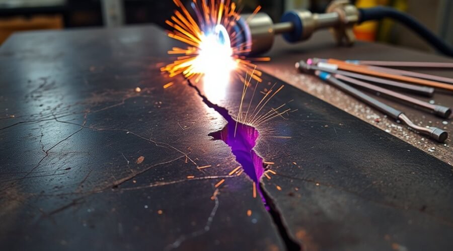
Welding cracks are localized fractures in the weld metal, fusion boundary, or heat-affected zone (HAZ). Because a crack has a sharp tip that concentrates stress, even a relatively small crack can become a serious weld defect. Common forms include solidification cracks, hydrogen-assisted cold cracks, longitudinal and transverse cracks, toe cracks, root cracks, and crater cracks.
Quick Answer
Welding cracks usually form when shrinkage or residual tensile stress acts on weld metal or a heat-affected zone that cannot accommodate the strain. Major contributors include solidification behavior, hydrogen, rapid cooling in hardenable steels, poor fit-up, high restraint, unsuitable filler metal, and contamination. Prevention depends on the material, joint design, welding procedure, consumable control, heat input, and cooling conditions.
Key Takeaways
- Weld cracks are fracture-type discontinuities and should be treated more seriously than many rounded imperfections such as isolated porosity.
- Hot or solidification cracks form while weld metal is solidifying or remains at high temperature; hydrogen-assisted cold cracks usually form after the joint has cooled substantially and may be delayed.
- Hydrogen cracking requires a combination of diffusible hydrogen, a susceptible microstructure, and tensile stress.
- Correct joint design, fit-up, low-hydrogen practice, suitable preheat when required, controlled heat input, and proper crater filling reduce cracking risk.
- A cracked structural or safety-critical weld should be evaluated and repaired under the applicable welding procedure, engineering specification, and inspection requirements.
What Are Welding Cracks?
Welding cracks are localized fractures or fracture-like discontinuities in a welded joint. They can occur in the weld metal, along the fusion boundary, or in the heat-affected zone beside the weld.
Cracks are among the most serious weld imperfections because their sharp tips concentrate stress and can allow damage to propagate under service loading.
Cracks may run parallel to the weld as longitudinal cracks, cross it as transverse cracks, begin at the weld toe or root, or form in the crater where the arc is stopped.
The mechanism matters as much as the location. A solidification crack forms while the weld metal is losing its remaining liquid film and cannot accommodate shrinkage strain. A hydrogen-assisted crack develops when diffusible hydrogen, a crack-sensitive microstructure, and tensile stress occur together in a susceptible material.
Accurate identification of the crack’s location, orientation, timing, and likely mechanism helps determine the correct inspection, repair, and prevention method.
Hot vs. Cold Weld Cracks
Hot and cold cracking are often discussed together, but they occur through different mechanisms. They should not be separated by a single universal temperature such as 1000°F or 600°F because the critical temperature range depends on the material and crack mechanism.
| Feature | Hot / Solidification Cracking | Hydrogen-Assisted Cold Cracking |
| Typical timing | During the final stages of solidification or at high temperature | After substantial cooling, often near ambient temperature; detection can be delayed |
| Typical drivers | Unfavorable weld-metal composition, solidification pattern, bead shape, shrinkage strain, and restraint | Diffusible hydrogen, a susceptible hard microstructure, and tensile stress |
| Common controls | Correct filler composition, bead shape, travel speed, joint design, and crater filling | Low-hydrogen practice, clean and dry consumables, appropriate preheat/interpass control, suitable heat input, and reduced restraint |
TWI’s guidance on solidification cracking explains that cracking occurs when the partly solidified weld cannot withstand contraction strain. Its hydrogen-cracking guidance identifies hydrogen, a susceptible microstructure, and tensile stress as the three key conditions for hydrogen cracking.
Why Weld Cracks Form During Cooling
Welding heats a relatively small zone to a much higher temperature than the surrounding material. The weld and nearby base metal then contract as they cool. When surrounding material restrains that contraction, tensile residual stresses develop.
Cracking becomes more likely when the metal has limited ductility at the same time those stresses are acting. The exact risk depends on material composition, thickness, restraint, joint geometry, heat input, cooling rate, and hydrogen level.
Thermal Contraction Stress
As a welded joint cools, the weld metal and heat-affected zone contract while surrounding cooler material resists that movement. This creates thermal contraction stress.
High restraint, thick sections, abrupt changes in section thickness, poor bead shape, and rigid joint geometry can all increase local strain. In hardenable steels, excessively rapid cooling can also create hard microstructures with reduced resistance to hydrogen-assisted cracking.
Useful controls include:
- Use the joint preparation and root opening specified by the welding procedure.
- Reduce unnecessary restraint where fabrication requirements allow it.
- Apply specified preheat and interpass-temperature controls uniformly.
- Use appropriate heat input, bead size, sequence, and travel speed.
- Avoid abrupt geometry changes that create severe stress concentrations.
Residual Stress Build-Up
Residual stresses remain in a welded component after it returns to ambient temperature. Local tensile residual stress can approach the material’s yield level and combine with service loading at crack-sensitive locations.
Residual stress alone does not mean a weld will crack. Cracking depends on the interaction between stress, material toughness or ductility, microstructure, defect geometry, temperature, environment, and—in hydrogen-assisted cracking—the amount of diffusible hydrogen.
Preheat can be valuable for susceptible ferritic steels because it slows the cooling rate, reduces the formation of very hard microstructures, and gives hydrogen additional time to diffuse from the weld region. Preheat should be selected from the applicable welding procedure or engineering guidance rather than guessed.
Post-weld heat treatment (PWHT) may be required for particular materials, thicknesses, service conditions, or construction codes. It should not be treated as a universal crack-prevention step.
Hydrogen Embrittlement Risk
Hydrogen-assisted weld cracking is most likely when three conditions occur together:
- Diffusible hydrogen enters the weld from consumables, moisture, contamination, or the welding process.
- A susceptible microstructure forms, often because a hardenable steel cools too rapidly.
- Tensile stress is present from shrinkage, residual stress, restraint, or external loading.
Possible hydrogen sources include damp low-hydrogen electrodes, contaminated joint surfaces, moisture, unsuitable consumable handling, and some welding processes or consumable types.
Preheat, when required by the procedure, slows cooling and can reduce hardness while allowing more hydrogen to diffuse away. Low-hydrogen consumables must also be stored and handled according to the manufacturer’s instructions.
Pro Tip: Do not choose a preheat temperature simply because a steel is “thick” or “high strength.” Material chemistry, carbon equivalent, thickness, restraint, diffusible-hydrogen level, heat input, and the governing welding procedure all matter.
How Poor Fit-Up Causes Cracks
Poor fit-up changes joint geometry, penetration conditions, weld volume, and restraint. These changes can increase stress concentration and make consistent welding more difficult.
The correct root opening, bevel angle, alignment, and land dimensions depend on the joint design and approved procedure. Both overly tight and overly wide joints can create problems.
Stress Concentration Risks
Misalignment and abrupt geometry changes disturb the intended load path through a joint. They can also force the welder to compensate with additional heat or weld metal, increasing distortion and residual stress.
- Keep alignment within the permitted fabrication tolerance.
- Use the specified root opening rather than an arbitrary “moderate” gap.
- Maintain consistent bevel geometry and root face.
- Avoid unnecessary restraint during assembly.
- Inspect fit-up before welding starts.
Gap Alignment Issues
A root opening that is too small can make root penetration or fusion difficult. An opening that is too large can increase weld-metal volume, distortion, burn-through risk, or restraint-related cracking depending on the process and joint. Misalignment can further change penetration and concentrate stress.
| Condition | Possible Effect |
| Root opening too small | Lack of root penetration or fusion |
| Root opening too large | Excess weld volume, burn-through, distortion, or increased restraint effects |
| Misalignment | Uneven load transfer and inconsistent fusion geometry |
| High restraint | Higher shrinkage stress and greater cracking risk |
| Incorrect preparation | Poor access, inconsistent penetration, and rework |
How Contamination Causes Weld Cracks
Contamination can interfere with fusion, shielding, weld-metal chemistry, and hydrogen control. Rust, oil, paint, grease, moisture, cutting fluids, and other contaminants should be removed to the degree required by the welding process and procedure.
In susceptible steel weld metals, elements such as sulfur and phosphorus can segregate during solidification and increase solidification-cracking susceptibility. The risk depends on weld composition, bead shape, solidification pattern, and imposed strain.
Moisture is especially important in hydrogen-sensitive applications because it can contribute hydrogen to the welding arc. Low-hydrogen electrodes therefore require controlled storage and handling.
Poor interpass cleaning can also trap slag or other nonmetallic material. Slag inclusions are a separate imperfection from cracks, but their geometry can produce stress concentration and reduce effective weld quality.
For gas-shielded processes, inadequate shielding can cause oxidation or porosity. Correct gas type, flow, equipment condition, torch position, and protection from excessive drafts are therefore important.
- Remove oil, paint, rust, moisture, and other prohibited contaminants.
- Keep consumables clean and dry according to manufacturer instructions.
- Remove slag between passes where the process produces slag.
- Maintain correct shielding-gas coverage.
- Use filler metal specified for the base material and procedure.
Types of Weld Cracks by Location
Cracks can be described by both location and mechanism. Location alone does not prove the cause, but it provides useful diagnostic information.
- Longitudinal cracks: run generally parallel to the weld axis. Centreline solidification cracking is a common example.
- Transverse cracks: cross the weld axis and may occur in the weld metal, heat-affected zone, or both.
- Root cracks: begin at or near the weld root and can result from several mechanisms, including hydrogen cracking or severe local stress.
- Toe cracks: start near the weld toe, where joint geometry and residual tensile stress can create a severe local stress concentration.
- Crater cracks: occur at the end of a weld bead when the crater is not adequately filled or the arc is terminated in a crack-sensitive condition.
- HAZ cracks: occur in the heat-affected base metal and are often associated with a crack-sensitive microstructure, hydrogen, stress, or material-specific metallurgical behavior.
Because different mechanisms can produce cracks in similar locations, a repair should address the root cause rather than merely covering the visible indication.
8 Ways to Prevent Weld Cracks
No single technique prevents every weld crack. A reliable approach controls material susceptibility, hydrogen, joint restraint, fit-up, consumables, and welding parameters together.
- Use the correct joint design. Avoid unnecessary restraint and abrupt geometry changes while following the qualified joint preparation.
- Verify fit-up before welding. Check root opening, alignment, bevel angle, root face, and tack condition against the procedure.
- Clean the joint properly. Remove prohibited oil, moisture, paint, rust, cutting residues, and other contamination before welding.
- Control consumable moisture. Store low-hydrogen electrodes in sealed containers or appropriate holding ovens and recondition only as the manufacturer permits.
- Apply specified preheat and interpass control. For susceptible steels, proper preheat can slow cooling, reduce hardness, and aid hydrogen diffusion.
- Use compatible filler metal. Weld-metal composition strongly affects solidification behavior, strength, toughness, and cracking susceptibility.
- Control heat input, bead shape, and travel speed. Avoid welding parameters that produce an unfavorable narrow/deep bead, excessive segregation, lack of fusion, or excessive hardening.
- Fill the crater before stopping. Use the process’s crater-fill technique or run-off method so the end of the weld has enough metal to resist shrinkage strain.
Note: The correct preheat, heat input, interpass temperature, filler metal, and inspection delay are material- and procedure-specific. Use the applicable WPS, manufacturer guidance, engineering specification, or construction code rather than a generic temperature copied from another material.
How to Inspect Welds for Cracks
Inspection normally begins with visual testing (VT). Good lighting, clean surfaces, proper access, and suitable magnification help reveal surface-breaking cracks at the weld face, toe, crater, and accessible root.
When visual inspection is not enough, the appropriate nondestructive testing method depends on the material, crack location, weld geometry, thickness, applicable code, and expected crack orientation.
| Method | Best Use | Important Limitation |
| Visual testing (VT) | Accessible surface-breaking indications | Cannot find hidden internal cracks |
| Liquid penetrant testing (PT) | Fine surface-breaking cracks on suitable nonporous materials | Only detects defects open to the surface |
| Magnetic particle testing (MT) | Surface and near-surface cracking in ferromagnetic materials | Not suitable for nonferromagnetic materials |
| Ultrasonic testing (UT) | Internal planar discontinuities in suitable weld geometries | Requires qualified technique, calibration, and interpretation |
| Radiographic testing (RT) | Volumetric weld examination and some crack orientations | Tight planar cracks may be difficult to reveal when poorly oriented to the radiation beam |
ISO 11666:2018 specifies ultrasonic acceptance levels for applicable full-penetration ferritic-steel welds. Acceptance criteria must still come from the governing code, specification, drawing, or contract rather than from appearance alone.
How to Spot Cracks Before They Spread
Early crack detection is based on inspection, not on waiting for obvious deformation or failure. Surface-breaking cracks often appear as sharp linear indications at the centreline, toe, root, or weld crater.
Irregular bead shape, undercut, distortion, or crater shape may identify areas that deserve closer inspection, but they are not proof that a crack exists. Likewise, discoloration by itself is not a reliable crack indicator.
Visual Crack Indicators
During visual inspection, look for:
- Fine linear fissures along or across the weld.
- Centreline openings in the weld bead.
- Branching or star-shaped cracking in the final crater.
- Cracks beginning at the weld toe.
- Visible root cracking where the root is accessible.
- Repeated cracking at tack welds, starts, stops, or restrained locations.
Clean the surface before deciding whether a dark line is a crack, slag line, scratch, arc strike, or harmless surface mark. When the indication remains uncertain, use a suitable NDT method.
Early NDT Detection
Liquid penetrant and magnetic particle testing can improve detection of fine surface-breaking cracks. Ultrasonic testing can locate many internal planar defects, while radiography can be useful for internal examination but may be less sensitive to tight cracks in unfavorable orientations.
Hydrogen-assisted cracking can be delayed. For materials and procedures where delayed cracking is a concern, inspection should occur after the delay period required by the applicable code or fabrication procedure rather than immediately after the weld merely becomes cool enough to touch.
TWI notes that hydrogen cracks may be very fine or subsurface and that the specified delay before inspection should be observed when delayed cracking is possible.
Repair Before Propagation
A confirmed weld crack should not simply be ground at the surface and covered with another weld bead. The full crack must be located and removed before rewelding.
- Determine the crack’s location, orientation, and extent.
- Identify the likely cause before selecting a repair procedure.
- Remove the crack by an approved method such as grinding, machining, or gouging where appropriate.
- Inspect the excavation to verify that the crack is completely removed.
- Restore the joint using the approved filler metal, preheat, heat input, interpass controls, and welding sequence.
- Perform the required post-repair inspection.
Warning: Do not weld directly over an existing crack in a structural, pressure-retaining, lifting, vehicle-safety, or other critical component. The visible end of a crack may not be its true end. Repair should follow the governing code, approved welding procedure, and required NDT or engineering evaluation.
How to Repair a Cracked Weld
A cracked weld should first be inspected to determine whether the indication is truly a crack, how far it extends, and whether the surrounding material has also been affected.
Step 1: Find the full crack. Use visual inspection and the appropriate PT, MT, UT, or RT method when needed. Do not rely only on the visible surface length.
Step 2: Identify the cause. Check material, filler metal, fit-up, restraint, preheat, heat input, consumable condition, contamination, bead shape, and welding sequence. Repairing the metal without correcting the cause can reproduce the same crack.
Step 3: Remove the crack completely. Grinding, machining, or carbon-arc gouging may be suitable depending on material and procedure. Removal should extend into sound metal and, where required, beyond the detected crack ends.
Step 4: Verify the excavation. Reinspect the prepared repair area before rewelding. This step confirms that no crack remains below the prepared surface.
Step 5: Prepare for rewelding. Clean the repair area, restore the required groove geometry, use the specified filler metal, and apply required preheat or interpass controls.
Step 6: Reweld using the approved procedure. Control heat input, bead placement, sequence, travel speed, and crater termination so the repair does not reproduce the original failure mechanism.
Step 7: Perform required post-weld treatment and inspection. PWHT should be performed only when the material, WPS, engineering specification, or code requires it. The repaired weld should then receive the required final inspection.
TWI’s crack-repair guidance notes that most codes require cracks to be removed before the excavation is rewelded, with sufficient additional removal to make sure the ends of the crack are eliminated.
Frequently Asked Questions
How do you prevent cracks in welding?
Prevent welding cracks by using the specified joint preparation and fit-up, cleaning the joint, controlling consumable moisture, choosing compatible filler metal, following required preheat and interpass temperatures, using appropriate heat input and travel speed, minimizing unnecessary restraint, and filling weld craters correctly. The exact controls depend on the base material and welding procedure.
What are seven common welding defects?
Seven commonly discussed welding imperfections are cracks, porosity, undercut, lack of fusion, slag inclusions, incomplete penetration, and overlap. Spatter is also common, but it is better treated separately rather than calling a list of eight items “seven defects.” Acceptance depends on the applicable fabrication standard and specified quality level.
What are the common causes of cracks in welding?
Common causes include solidification shrinkage, unfavorable weld-metal chemistry, high joint restraint, diffusible hydrogen, rapid cooling in hardenable steels, unsuitable filler metal, poor joint geometry, incorrect welding parameters, contamination, and poorly filled weld craters. More than one factor often acts at the same time.
Why should you not coat welding rods with WD-40?
Welding electrodes should not be coated with WD-40 as a moisture-control method. Oil or petroleum residue can contaminate the welding process, and WD-40 aerosol is flammable. Low-hydrogen electrodes should instead be kept in hermetically sealed packaging or suitable holding ovens and reconditioned only according to the electrode manufacturer’s instructions.
Can cold cracks appear after welding is finished?
Yes. Hydrogen-assisted cracking can be delayed and may not be detectable immediately after welding. Susceptible welds should therefore be inspected after the delay period required by the governing fabrication code or welding procedure.
Can you simply weld over a cracked weld?
No. Welding over a crack can leave part of the crack trapped beneath the repair and does not correct its underlying cause. The crack should be fully located, removed into sound metal, verified as removed, and then rewelded using the appropriate repair procedure.
Conclusion
Welding cracks are serious defects because they concentrate stress and can propagate under service loading. Preventing them requires more than one technique: joint design, fit-up, material selection, hydrogen control, consumable storage, heat input, cooling rate, restraint, and welding sequence all affect crack susceptibility.
When a crack is found, identify its full extent and probable cause before repairing it. Remove the crack into sound metal, verify the excavation, reweld under the appropriate procedure, and perform the required final inspection. For structural, pressure-retaining, lifting, vehicle-safety, or other critical work, follow the governing welding code and qualified repair procedure rather than relying on a generic repair method.
Sources
- TWI — Defects: Solidification Cracking — solidification-crack mechanisms, detection, prevention, and repair.
- TWI — Hydrogen Cracks in Steels: Prevention and Best Practice — hydrogen-cracking conditions, preheat, consumable control, inspection, and repair.
- ISO 5817:2023 — current quality-level standard for imperfections in applicable fusion-welded joints.
- ISO 11666:2018 — ultrasonic-testing acceptance levels for applicable welded joints.
- Hobart Brothers — Storage and Reconditioning Electrodes — proper electrode moisture control, storage, and reconditioning.
- WD-40 Company Safety Data Sheet — product flammability and ignition precautions.