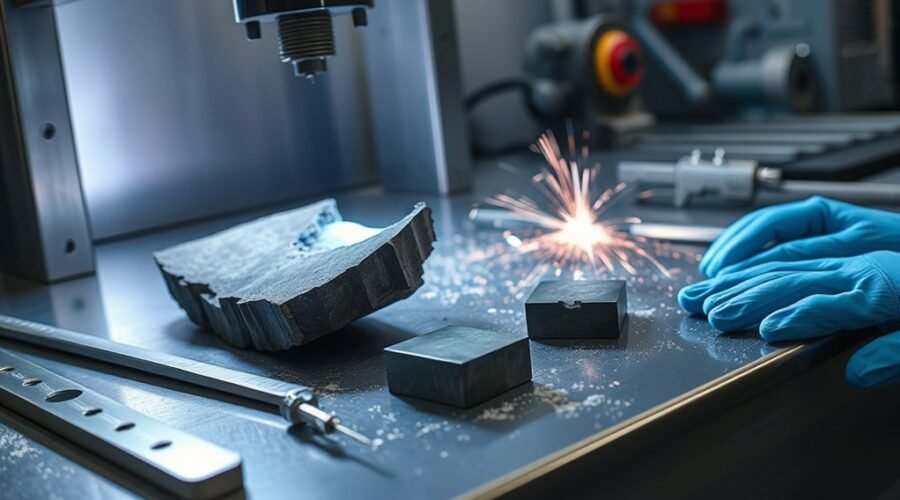
Destructive weld testing gives inspectors direct evidence of how a welded joint behaves when it is bent, pulled, fractured, sectioned, or otherwise tested beyond normal service conditions. Depending on the method, testing can measure strength and ductility or expose fusion boundaries, penetration, porosity, cracking, inclusions, and other discontinuities. The correct test and acceptance criteria depend on the governing welding code, material, joint type, and purpose of the qualification.
Quick Answer
Destructive weld testing intentionally bends, pulls, fractures, cuts, or otherwise damages a representative weld specimen so its strength, ductility, fusion, penetration, and internal condition can be evaluated. Common methods include guided bend, transverse tensile, fracture or break, macroetch, impact, and hardness tests. Pass/fail criteria come from the applicable welding code or specification.
Key Takeaways
- Destructive weld testing sacrifices a coupon or specimen to obtain direct evidence about weld strength, ductility, fusion, penetration, fracture behavior, or metallurgical condition.
- Common methods include guided bend, transverse tensile, macroetch, fracture or break, impact, hardness, and application-specific shear tests.
- There is no universal rule that a weld passes when it reaches 90% of the base-metal strength; acceptance criteria depend on the governing code or specification.
- Macroetch and fracture tests reveal different information: an etched cross-section shows features intersecting one plane, while a fracture surface can expose internal discontinuities over the broken area.
- Destructive testing and nondestructive testing are complementary. One does not automatically replace the other.
- Specimen preparation, sampling location, test equipment, safety controls, and documentation are essential to obtaining valid results.
What Is Destructive Weld Testing?
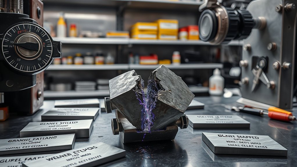
Destructive weld testing is a physical evaluation process in which a representative welded specimen is intentionally bent, pulled, fractured, sectioned, machined, or otherwise damaged so its properties and internal condition can be examined. Unlike an inspection method designed to leave the component serviceable, destructive testing accepts the loss of the test piece in exchange for direct mechanical or cross-sectional evidence.
The information obtained depends on the test. A transverse tensile test measures the tensile strength of a welded butt joint and records where fracture occurs. A guided bend test places the weld and heat-affected regions under severe deformation so surface-breaking imperfections and inadequate ductility can become visible. A macroetch examination exposes weld geometry, penetration, fusion boundaries, and other features on a prepared cross-section. Fracture tests expose a broken surface so internal imperfections can be inspected.
The test method tells you what to measure; the governing code or specification tells you what constitutes an acceptable result.
Destructive testing is widely used for welding procedure qualification, welder or welding-operator performance qualification, research, production sampling, process development, and failure analysis. It is especially useful when engineers need evidence about mechanical performance or internal weld structure that cannot be obtained from surface appearance alone.
Why Destructive Weld Testing Matters
A weld can look acceptable from the outside while still containing inadequate fusion, incomplete penetration, internal porosity, inclusions, unfavorable hardness, poor ductility, or other conditions that affect performance. Destructive testing provides a controlled way to evaluate those characteristics on representative specimens.
For procedure qualification, testing can demonstrate whether a particular combination of base material, filler metal, joint design, position, heat input, preheat, interpass control, and other essential variables produces acceptable results. For welder performance qualification, bend, fracture, macroetch, or other permitted tests can demonstrate whether the welder can produce welds that satisfy the applicable requirements.
Current structural-steel requirements in the United States are commonly governed by AWS D1.1/D1.1M:2025-AMD1, Structural Welding Code—Steel when that code is specified by the contract. AWS D1.1 contains qualification, testing, inspection, and acceptance provisions for structural-steel work. Other industries may use different AWS codes, ASME requirements, ISO standards, military specifications, customer specifications, or project-specific procedures.
Pro Tip: Identify the governing code and edition before cutting a test coupon. The code determines the required specimens, dimensions, orientation, number of tests, test procedure, and acceptance criteria. Testing first and looking for a pass/fail rule afterward can invalidate the qualification.
How Destructive Weld Testing Works
The exact sequence varies by standard, but most destructive weld evaluations follow the same general path:
- Select or produce the test coupon. The coupon must represent the required joint, material, welding process, position, thickness, and variables specified by the governing procedure or qualification code.
- Mark specimen locations. Orientation and extraction location matter because the weld metal, fusion boundary, and heat-affected zone may behave differently.
- Remove and prepare specimens. Specimens may be saw-cut, machined, ground, polished, notched, or etched according to the applicable test standard.
- Perform the required test. The specimen may be pulled in tension, bent around a former, fractured, impact-tested, hardness-tested, or sectioned for macro examination.
- Measure and inspect the result. Depending on the method, technicians record load, tensile strength, absorbed impact energy, hardness, fracture location, discontinuity dimensions, weld geometry, or visible indications.
- Compare the findings with acceptance criteria. Results are judged against the applicable code, specification, procedure, drawing, or customer requirement rather than a generic percentage.
- Document the test. Qualification records normally identify the material, weld procedure, specimen type, test results, observations, and disposition.
A test coupon is not always the same thing as the final test specimen. One welded plate or pipe coupon may be cut into several individual specimens for tension, bend, impact, macroetch, or other tests.
The Most Common Destructive Weld Tests
Different destructive tests answer different questions. No single test proves every aspect of weld quality.
| Test | Main Purpose | Typical Information |
|---|---|---|
| Guided bend | Ductility and weld soundness under severe deformation | Surface-opening cracks, lack of fusion, incomplete penetration, and other exposed imperfections |
| Transverse tensile | Joint tensile strength | Maximum load, calculated tensile strength, and fracture location |
| Macroetch | Cross-sectional weld examination | Penetration, fusion boundaries, weld size, HAZ, geometry, and discontinuities intersecting the section |
| Fracture / break | Internal soundness on a fracture surface | Porosity, cracks, lack of fusion, incomplete penetration, and inclusions |
| Impact | Notch toughness | Energy absorbed during rapid fracture at a specified temperature |
| Hardness | Local resistance to indentation | Hardness distribution through weld metal, HAZ, and base metal |
Macro Etch Testing
Macroetch testing examines a prepared cross-section through a welded joint. The section is cut and prepared to the required surface condition, then treated with a suitable etchant so differences between the weld metal, fusion boundary, heat-affected zone, and base metal become easier to see.
ISO 17639:2022 provides recommendations for specimen preparation and macroscopic and microscopic examination of welds. Depending on the joint and specification, a macro section can reveal weld size, penetration profile, fusion, root condition, reinforcement, heat-affected-zone geometry, and imperfections that intersect the examined plane.
A macroetch is highly useful, but it is still a two-dimensional section. An internal pore or inclusion located away from the cut plane may not appear in that particular section. For that reason, macroetch results should not be interpreted as proof that the entire weld volume is defect-free.
Bend and Break Tests
Bend and break tests place a welded specimen under controlled deformation or fracture so imperfections that are difficult to judge from the exterior can be exposed.
Guided bends are commonly prepared as face, root, or side bends, depending on the material thickness and governing procedure. The specimen is bent around a specified former or within a specified fixture. The surface placed in tension is then examined and any relevant discontinuities are measured against the applicable acceptance criteria.
Break tests intentionally fracture a specimen so the newly exposed fracture surface can be inspected. Fillet-weld fracture tests and other fracture-test arrangements can reveal lack of fusion, incomplete penetration, porosity, cracks, and inclusions.
Acid Etch and Macro Etch Tests
In weld examination, “acid etch” is often used informally to describe an etching step used during macrographic or micrographic examination. The important point is that the technique normally involves a properly prepared weld cross-section and an etchant suitable for the material being examined.
The etchant produces contrast between metallurgical regions so the weld profile becomes easier to evaluate. Depending on material and preparation, the examiner may assess:
- fusion boundaries;
- depth and shape of penetration;
- weld size and throat;
- root condition;
- heat-affected-zone location;
- cracks, porosity, inclusions, or incomplete fusion that intersect the prepared plane; and
- other cross-sectional features required by the applicable procedure.
Undercut is primarily a surface-profile discontinuity and is normally detectable through visual inspection or dimensional examination. Etching should not be described as the primary method for finding ordinary external undercut.
Warning: Weld specimen preparation can involve cutting, grinding, machining, chemicals, high loads, and intentional fracture. Follow the test laboratory’s written procedure, machine-guarding requirements, chemical Safety Data Sheets, ventilation requirements, and required eye, face, hand, and body protection. Fractured specimens can produce sharp edges or flying fragments.
Bend Tests for Weld Ductility
Guided bend testing subjects a prepared weld specimen to severe controlled deformation so ductility and weld soundness can be evaluated. ISO 5173:2023 specifies methods for transverse root, face, and side bend testing and also addresses alternative arrangements for welded joints where the materials have significantly different bending behavior.
A face-bend specimen generally places the weld face on the tension side of the bend. A root-bend specimen places the weld root on the tension side. A side-bend specimen exposes a transverse section of the weld through the thickness to tension during bending.
As the specimen bends, lack of fusion, incomplete penetration, cracking, or other imperfections may open at the tension surface. The bend radius, former diameter, specimen dimensions, bend angle, and acceptance limits are determined by the applicable standard or code.
There is no universal rule that every visible indication automatically fails a bend test. Relevant indications are measured and evaluated using the specified acceptance criteria. Certain standards distinguish between defects located in the weld, at corners, or at specimen edges.
Free-bend or other bend arrangements may appear in particular specifications or historical procedures, but modern qualification work should follow the exact bend method required by the governing document rather than substituting a generic bend test.
Tensile and Shear Strength Tests
Transverse tensile testing measures the tensile capacity of a welded butt joint by pulling a prepared specimen until it fractures. ISO 4136:2022 specifies specimen dimensions and the procedure used to determine the tensile strength and fracture location of welded butt joints.
- The specimen’s required dimensions are measured.
- The specimen is mounted in a calibrated tensile-testing machine.
- Axial load is increased until the specimen fractures.
- The maximum load is recorded.
- Tensile strength is calculated from the applicable original cross-sectional area.
- The fracture location and appearance are documented where required.
- The result is compared with the governing acceptance requirement.
There is no universal “90% of base-metal strength” pass rule. Required strength depends on the welding code, material specification, qualification rules, and fracture location. A result that is acceptable under one code or material combination may not satisfy another.
Shear or lap-shear tests are used for certain joint types and welding processes, including some lap joints, resistance welds, brazed joints, adhesives, and specialized qualification programs. The loading arrangement and reported value may be force, stress, or another specified measure. Shear testing should therefore be described in relation to the specific joint and standard rather than as a universal groove-weld qualification test.
Nick Break and Fillet Break Tests
Fracture tests intentionally break a welded specimen so the internal fracture surface can be examined. They are particularly useful for exposing discontinuities that may not be visible on the outside of the weld.
Nick Break Evaluation
A nick-break-type test uses a prepared specimen with notches or another permitted fracture-initiation arrangement. Load is applied until the specimen breaks through the weld region, exposing the fracture surface.
ISO 9017:2017 specifies fracture-test procedures intended to provide information about the type, size, and distribution of internal imperfections such as porosity, cracks, lack of fusion, lack of penetration, and solid inclusions.
- Prepare and identify the specimen according to the applicable procedure.
- Introduce any required notch or fracture-initiation feature.
- Load the specimen using the prescribed arrangement.
- Allow the weld region to fracture.
- Inspect and measure relevant indications on the exposed surface.
- Compare them with the specified acceptance limits.
The purpose is not simply to make the specimen fail. The value comes from controlling where and how it fractures and from evaluating the exposed surface consistently.
Fillet Break Analysis
A fillet-weld break test loads a welded assembly until the fillet weld or adjoining region opens sufficiently for the root and fracture surface to be examined. Depending on the governing qualification procedure, the examiner may evaluate fusion at the root, porosity, inclusions, cracking, weld size, and other specified discontinuities.
Fillet-break tests are frequently used in welder or welding-operator qualification because they provide a direct view of whether fusion was achieved at regions that cannot be fully evaluated from external appearance alone.
Acceptance limits are code-specific. The fracture location itself should also be interpreted carefully because failure can occur in weld metal, the fusion zone, heat-affected base metal, or unaffected base metal for different reasons.
Impact and Hardness Tests
Impact Testing
Impact testing evaluates notch toughness, or the ability of a material to absorb energy during rapid fracture. In welded-joint qualification, Charpy V-notch specimens may be taken from specified locations in the weld metal or heat-affected zone and tested at a required temperature.
ISO 9016:2022 addresses specimen location, notch orientation, examination, and reporting for impact tests on welded butt joints. Impact requirements are especially important where structures may experience low temperatures, dynamic loading, brittle-fracture risk, or project-specific toughness requirements.
Impact acceptance is normally based on requirements such as minimum absorbed energy, test temperature, specimen location, and the governing code or material specification. It should not be inferred from tensile or bend results alone.
Hardness Testing
Hardness testing measures local resistance to indentation and can reveal changes produced by welding thermal cycles. Measurements may be taken across the base metal, heat-affected zone, and weld metal.
Hardness testing is useful when excessive HAZ or weld-metal hardness could indicate an increased risk of cracking, when a procedure limits hardness for service reasons, or when engineers need to map hardness changes across a welded joint.
The required test method, load, spacing, number of impressions, and maximum or minimum permitted values depend on the material and governing standard. A hardness reading by itself does not prove overall weld quality; it answers a specific metallurgical or service-related question.
Why Specimen Location and Preparation Matter
A destructive test is only as representative as the specimen used. Removing the wrong section, overheating the specimen while cutting, leaving machining marks in a critical region, changing the required specimen thickness, or placing an impact notch in the wrong location can make the test invalid or misleading.
Important preparation controls can include:
- traceability from the original test coupon to each specimen;
- correct orientation relative to the weld axis;
- specified location through the plate or pipe thickness;
- controlled cutting so the test region is not unintentionally altered;
- required removal or retention of weld reinforcement;
- specified edge radius and surface finish for bend specimens;
- accurate tensile-specimen dimensions;
- correct notch location and orientation for impact testing; and
- proper polishing and etching for macro or micro examination.
If preparation does not meet the specified test method, the laboratory should determine whether the specimen can be re-prepared or whether a replacement specimen or new coupon is required.
How to Read Weld Test Results
Weld test results should be read by comparing the measured result with the exact acceptance criteria in the applicable welding code, material specification, procedure, drawing, or contract document.
| Test Result | What to Evaluate | Do Not Assume |
|---|---|---|
| Tensile fracture | Maximum load, calculated tensile strength, fracture location | That 90% of base-metal strength is universally acceptable |
| Bend indication | Type, size, number, and location of indications | That every visible indication automatically fails |
| Macroetch feature | Fusion, penetration, weld size, HAZ, geometry, visible imperfections | That one clean section proves the entire weld volume is defect-free |
| Fracture surface | Porosity, fusion, penetration, cracks, inclusions, fracture path | That fracture in one location always has the same cause |
| Impact value | Absorbed energy, temperature, notch location and orientation | That acceptable tensile strength guarantees adequate toughness |
| Hardness reading | Location, test load, hardness profile and specified limits | That a single hardness value represents the entire joint |
When a result falls outside the acceptance criteria, the next step is not automatically to blame the welder. Investigators may need to review specimen preparation, equipment calibration, material identity, heat treatment, welding parameters, joint preparation, consumables, preheat, interpass temperature, heat input, or other variables.
Note: A failed or abnormal test should first be checked for test validity. Codes may distinguish between a genuine qualification failure and a test that is invalid because of specimen preparation, equipment, or testing problems. Retesting must follow the governing document rather than an improvised repeat-test rule.
Codes and Acceptance Criteria
Destructive testing is not governed by one universal pass/fail standard. Requirements depend on the industry and contract. A structural-steel qualification may use AWS D1.1, while pressure equipment, pipelines, aerospace components, transportation products, offshore structures, or international projects may use different standards.
The governing document can specify:
- coupon dimensions and joint design;
- required welding position;
- base and filler materials;
- number and location of specimens;
- tension, bend, impact, fracture, macroetch, hardness, or other required tests;
- specimen dimensions and preparation;
- test-machine and fixture requirements;
- acceptance criteria;
- conditions for retesting; and
- required qualification records.
This is why generalized statements such as “a weld must reach 90% of base-metal strength” should not be used without identifying the exact code or specification that establishes that criterion.
Where Destructive Weld Testing Is Used
Destructive weld testing is used in many industries, but the purpose varies.
- Welding procedure qualification: Demonstrates that a proposed welding procedure can produce joints meeting specified mechanical and quality requirements.
- Welder and welding-operator qualification: Demonstrates the ability to deposit an acceptable weld using the qualified process and required variables.
- Production sampling: Representative coupons or sample parts may be destructively tested as part of manufacturing quality control.
- Research and development: Engineers compare welding parameters, filler materials, joint configurations, heat treatments, and new processes.
- Failure analysis: Sections and fracture surfaces can help determine how and where a failed joint cracked or separated.
- Automotive and transportation manufacturing: Peel, chisel, tensile-shear, cross-tension, sectioning, or other process-specific tests may be used for spot welds and production joints.
- Structural fabrication: Bend, tension, macroetch, fracture, and toughness testing may be required for procedure or personnel qualification under the applicable code.
Because the tested specimen is consumed, production structures are normally not broken simply to prove that they are acceptable. Instead, qualification coupons, sacrificial samples, witness coupons, procedure-test assemblies, or specifically selected samples are used when destructive testing is required.
Limitations of Destructive Weld Testing
Destructive testing is powerful, but it has important limitations.
- The specimen is lost. The tested piece cannot normally return to service.
- Sampling may not represent every weld. A successful coupon does not guarantee that every production weld is identical.
- Preparation affects results. Poor machining, cutting, polishing, notching, or specimen orientation can invalidate a test.
- Different tests reveal different properties. Tensile strength does not prove toughness; a macroetch does not measure tensile strength; a bend test does not inspect the entire weld volume.
- Testing can be time-consuming and costly. Laboratories may require machining, calibrated equipment, controlled temperatures, trained personnel, and detailed records.
- Acceptance is specification-dependent. A technically interesting result is not automatically a code-compliant result.
For these reasons, destructive testing is normally part of a broader quality system that can also include procedure control, welder qualification, visual inspection, NDT, material traceability, calibration, and production records.
Destructive Testing vs. NDT
Destructive testing and nondestructive testing answer different questions. Destructive methods intentionally sacrifice a specimen to measure mechanical behavior or expose an internal section or fracture surface. NDT evaluates a component without intentionally destroying its ability to remain in service.
Failure-Based Evaluation
Destructive tests can directly measure properties such as tensile strength, impact toughness, and hardness or can reveal weld structure after sectioning or fracture. Typical examples include:
- guided bend testing;
- transverse tensile testing;
- macroetch examination;
- fracture or break testing;
- impact testing; and
- hardness testing.
These methods are especially valuable during qualification, process development, research, production sampling, and failure analysis.
Damage-Free Inspection
Nondestructive testing is used when the inspected component must remain usable. Depending on material, geometry, code, and defect type, methods can include visual testing, liquid penetrant testing, magnetic-particle testing, ultrasonic testing, and radiographic testing.
| Method | Component Remains Serviceable? | Typical Purpose |
|---|---|---|
| Visual testing | Yes | Surface condition, profile, dimensions, visible discontinuities |
| Magnetic-particle testing | Yes | Surface and near-surface discontinuities in suitable ferromagnetic materials |
| Ultrasonic testing | Yes | Internal reflectors and weld discontinuities where the technique is applicable |
| Radiographic testing | Yes | Volumetric imaging of internal features and discontinuities |
| Guided bend | No | Ductility and exposed imperfections after severe deformation |
| Fracture / break test | No | Internal imperfections exposed on a fracture surface |
NDT should not be dismissed as merely preliminary. In many production applications, the governing construction code specifically requires NDT and provides acceptance criteria for it. Likewise, a destructive qualification test does not eliminate the need for production inspection.
Method Selection Factors
Method selection depends on what engineers need to know.
- Required property: Strength, ductility, toughness, hardness, fusion, penetration, or internal soundness.
- Component status: Qualification coupon, sacrificial sample, research specimen, or completed production component.
- Material and joint geometry: Some techniques are unsuitable for particular materials or joint configurations.
- Governing code: The required test may already be specified.
- Defect orientation and location: Different inspection methods have different sensitivities.
- Cost and schedule: Machining, laboratory work, calibration, and specimen replacement may affect the test plan.
- Safety and access: High test loads, radiation, chemicals, sharp specimens, temperature conditioning, or limited access may require additional controls.
In many quality programs, the strongest approach is not “destructive testing or NDT” but an appropriate combination of procedure qualification, destructive testing, visual inspection, NDT, and process control.
Frequently Asked Questions
What are the different methods used for destructive weld testing?
Common methods include guided bend testing, transverse tensile testing, macroetch or macrographic examination, fracture or break testing, impact testing, hardness testing, and application-specific shear tests. The required method depends on the joint, material, welding process, qualification purpose, and governing standard.
What are destructive testing methods?
Destructive testing methods intentionally damage or consume a representative test specimen so engineers can measure mechanical properties or directly inspect a cross-section or fracture surface. Examples include tension, bend, impact, hardness, macroetch, and fracture testing.
What are the three basic types of destructive testing?
There is no universal welding standard that limits destructive testing to exactly three basic types. Tensile, bend, and impact tests are important mechanical tests, but weld evaluation also commonly uses fracture, macrographic, hardness, and other specialized tests.
What are the two main types of welding testing methods?
At a broad level, weld examination is often grouped into destructive testing and nondestructive testing. Destructive testing consumes or permanently deforms the specimen, while NDT evaluates a weld without intentionally making the component unusable. The two approaches are complementary and may both be required by the governing code.
Does a weld pass if it reaches 90% of the base-metal tensile strength?
Not as a universal rule. Weld tensile-test acceptance depends on the applicable code, material specification, procedure qualification requirements, specimen geometry, and sometimes the location of fracture. Always use the acceptance criteria specified by the governing document rather than a general 90% rule.
Which standard should be used for destructive weld testing?
Use the standard required by the project, industry, contract, or regulatory framework. Examples include AWS welding codes for specific structural applications and ISO standards such as ISO 4136 for transverse tensile tests, ISO 5173 for bend tests, ISO 17639 for macro/micro examination, and ISO 9017 for fracture tests.
Conclusion
Destructive weld testing turns a representative welded specimen into measurable evidence about joint performance and internal condition. Guided bends evaluate severe deformation and exposed imperfections; tensile tests measure joint strength and fracture location; macroetch sections show penetration, fusion boundaries, weld geometry, and heat-affected regions; fracture tests expose internal discontinuities; and impact and hardness tests answer additional toughness and metallurgical questions.
The most important rule is to judge every test against the correct governing code or specification. There is no universal 90% tensile-strength threshold, no single destructive test that proves every aspect of weld quality, and no reason to treat destructive testing and NDT as competing approaches. Used together with sound procedures, qualified personnel, calibrated equipment, and proper inspection, these methods provide a defensible basis for welding qualification and quality control.
Sources
- American Welding Society — AWS D1.1/D1.1M:2025-AMD1 — current structural-steel welding, qualification, inspection, and acceptance-code context.
- ISO 4136:2022 — Transverse tensile test — specimen and procedure requirements for determining welded butt-joint tensile strength and fracture location.
- ISO 5173:2023 — Bend tests — root, face, side, and related bend-test methods for welded metallic materials.
- ISO 17639:2022 — Macroscopic and microscopic examination of welds — specimen preparation and examination guidance for weld cross-sections.
- ISO 9017:2017 — Fracture test — fracture-testing procedures for exposing and evaluating internal weld imperfections.
- OSHA — Welding, Cutting, and Brazing: Hazards and Solutions — welding-related physical, eye, fume, burn, and PPE safety guidance.