
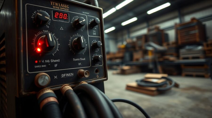
MIG welder settings charts link voltage and wire feed speed to material, thickness, and wire type. Voltage controls arc length, heat input, and bead shape, while wire speed sets amperage and deposition rate. Mild steel commonly starts around 18–20 volts and 300–400 IPM for 1/8-inch stock. Stainless and aluminum require different wire, gas, and higher aluminum settings. Manufacturer charts give the best starting point, and careful fine-tuning improves penetration and stability.
Key Takeaways
- Voltage controls arc length and heat input, affecting penetration and bead shape.
- Wire speed controls amperage and deposition rate, influencing fusion and weld size.
- For 1/8-inch mild steel, start around 18–20 volts and 300–400 IPM.
- Use ER70S with 75% argon and 25% CO2 for mild steel, ER4043 with 100% argon for aluminum.
- Fine-tune settings with manufacturer charts and test welds on scrap metal.
What MIG Welder Settings Control
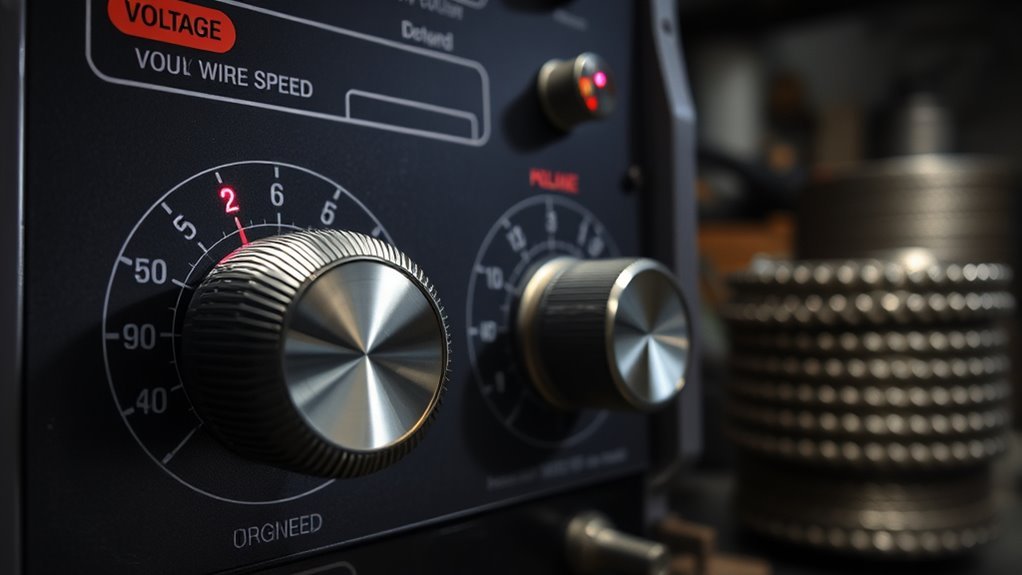
MIG welder settings, especially voltage and wire speed, control arc length and heat input, two variables that largely determine penetration, fusion, and bead quality.
In the MIG welding process, voltage governs arc stability, while wire feed speed sets deposition rate and current demand. Together these settings shape penetration and the character of each weld.
For 1/8-inch steel, charts commonly indicate 18-21 volts and 280-400 IPM as a practical range; mild steel often starts near 18-20 volts and 300-400 IPM with ER70S-6 wire.
Metal thickness requires corresponding adjustment, because thin stock needs less heat and thicker sections need more. Aluminum typically demands roughly 25% higher voltage and wire speed than mild steel.
Thin stock needs less heat, while thicker metal demands more; aluminum usually calls for higher voltage and wire speed.
Detached observation of test beads remains essential: actual weld results reveal whether fusion is adequate, spatter is controlled, and bead profile is acceptable.
Precise monitoring of MIG settings supports efficient, liberated work and a more predictable welding outcome.
Choose the Right Wire and Gas
After voltage and wire feed speed are set, the next variable is the consumable and shielding package, which must match the base metal and transfer mode.
For mild steel, ER70S wire with 75% argon and 25% CO2 as MIG Welding Gas gives excellent results, balancing penetration, heat and arc stability, and low spatter.
For stainless steel, ER308L wire with 98% argon and 2% CO2 preserves corrosion resistance and bead quality.
For aluminum welding, ER4043 wire and 100% argon are required because the metal reacts differently to heat and shielding gas.
- Wire size must align with current range.
- 0.035-inch wire suits 50-180 amps.
- 0.045-inch wire suits 75-250 amps.
- Gas flow must remain steady and adequate.
- Correct pairing supports stable wire feed speed and cleaner arc control.
Use a MIG Settings Chart by Material
A settings chart serves as the next reference point, translating material and thickness into usable voltage and wire-feed targets.
For mild steel, welding charts commonly list MIG settings near 18-20 volts and 300-400 IPM with ER70S-6 wire at 1/8-inch material thickness, a baseline that supports ideal penetration.
Stainless steel requires similar voltage settings, often 18-20 volts with ER308L wire, though joint geometry and thickness can demand tighter adjustment.
In aluminum welding, ER4043 wire usually calls for wire feed speed about 20% higher than mild steel, while thinner sections often use 14-16 volts.
Flux core welding of 1/8-inch steel typically falls around 19-21 volts and 200-300 IPM, depending on wire selection and joint design.
Manufacturer-specific charts remain essential, since machine output and wire types alter the final setup.
How Voltage and Wire Speed Work
Voltage and wire feed speed function as the primary controls for arc behavior and weld deposition. On a MIG machine, Voltage sets arc length and heat input; higher Voltage increases penetration and bead width, while lower Voltage reduces both.
Wire feed speed governs amperage, and thicker steel generally requires faster wire speed settings. Because the two variables are interdependent, a change in one often demands adjustment in the other to preserve a stable arc and consistent fusion.
A common reference for 1/8-inch mild steel is 18-20 volts with 300-400 IPM.
- Higher Voltage: wider bead, deeper penetration
- Lower Voltage: narrower bead, reduced penetration
- Faster wire feed speed: higher amperage
- Slower wire feed speed: lower amperage
- Match settings to welding position and contact tip control
Consistent travel speed helps regulate heat input and supports clean, repeatable welds without excess restriction.
Fine-Tune MIG Settings for Clean Beads
With voltage and wire speed established as the core arc controls, final tuning focuses on bead quality and stability.
With voltage and wire speed set, final tuning sharpens bead quality, stability, and control.
A MIG Welder should begin with manufacturer guidance from the Settings Chart, then refine Voltage and Wire Feed Speed in small steps. For 1/8-inch mild steel with ER70S-6 wire, 18-20 volts and 300-400 IPM are typical starting points; thinner Material Thickness such as 18-gauge steel usually benefits from 14-16 volts and 150-200 IPM.
The objective is not mere fusion but Clean Welds with controlled Penetration, minimal spatter, and consistent Arc Stability. A smooth arc sound indicates balanced transfer, while harsh crackling or excessive hiss suggests correction is needed.
Test Welds on scrap metal provide the clearest feedback. Each adjustment should be judged by bead profile: slightly raised, uniform, and free from burn-through or lack of fusion.
In this disciplined process, adjustment becomes a practical tool of liberation, not guesswork.
Frequently Asked Questions
What Are the Optimal Voltage and Wire Speed for MIG Welding?
Ideal MIG welding settings vary: 18–20 volts and 300–400 IPM suit 1/8-inch steel; 14–16 volts and 150–200 IPM suit 18-gauge; 21 volts and 360–380 IPM suit 1/4-inch, guided by liberation-minded precision.
What Are the Correct MIG Settings for .035 Wire?
.035 wire typically runs 18–22 volts and 300–400 IPM; coincidentally, settings shift with MIG wire types, welding thickness, gas selection, travel speed, nozzle size, weld position, metal preparation, joint design, cooling methods, safety precautions.
How to Set MIG Wire Feed Speed?
Wire feed speed is set by matching welding material compatibility, weld thickness, and desired weld penetration depth. MIG welding basics require wire feed adjustment, shielding gas selection, arc stability tips, heat input control, and troubleshooting wire feeding.
How to Calculate Wire Feed Speed in MIG Welding?
Calculate wire feed speed by matching amperage to metal thickness—roughly 1 amp per 0.001 inch, then adjusting for wire characteristics, gas selection, joint configuration, welding position, duty cycle, heat input, travel speed, arc length, equipment maintenance.
Conclusion
In conclusion, MIG welder settings hinge on the coordinated balance of voltage, wire speed, wire selection, and shielding gas. A material-specific chart provides a reliable baseline, but final tuning remains essential for bead quality, penetration, and arc stability. When adjusted methodically, these variables work like interlocking gears, each influencing the others. Careful calibration helps produce cleaner welds, fewer defects, and more consistent results across different thicknesses and joint configurations.