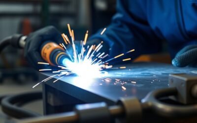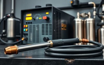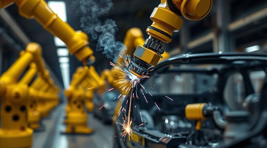
Robotic welding uses a programmable industrial robot to move a welding torch, gun, or workpiece through a controlled path while the welding power source and other equipment manage the joining process. It can improve repeatability, throughput, worker separation from welding hazards, and process consistency, but the strongest results come from parts with stable geometry, reliable fit-up, suitable fixtures, and enough production demand to justify automation.
Quick Answer
Robotic welding is best suited to repeatable parts that can be located consistently in a fixture and welded with stable parameters. A complete cell typically combines a robot, welding equipment, fixtures or positioners, controls, safety systems, and often sensing. It can raise throughput and consistency, but cost and ROI depend on the complete production cycle.
Key Takeaways
- Robotic welding delivers the most value when parts, joints, fixtures, and production volumes are repeatable.
- A welding robot is only one part of the cell; the power source, torch, wire or electrode delivery, shielding gas, fixtures, positioners, controls, and safeguarding also affect performance.
- GMAW/MIG is common for high-production arc welding, while GTAW/TIG, FCAW, PAW, laser welding, and resistance spot welding suit different materials and applications.
- Robot speed alone does not determine productivity. Load/unload time, part fit-up, positioner movement, cleaning, inspection, maintenance, and changeovers all affect cycle time.
- There is no dependable universal price, payback period, speed multiplier, or consumable-saving percentage for robotic welding; these should be calculated from the proposed cell and the plant’s real production data.
What Is Robotic Welding?
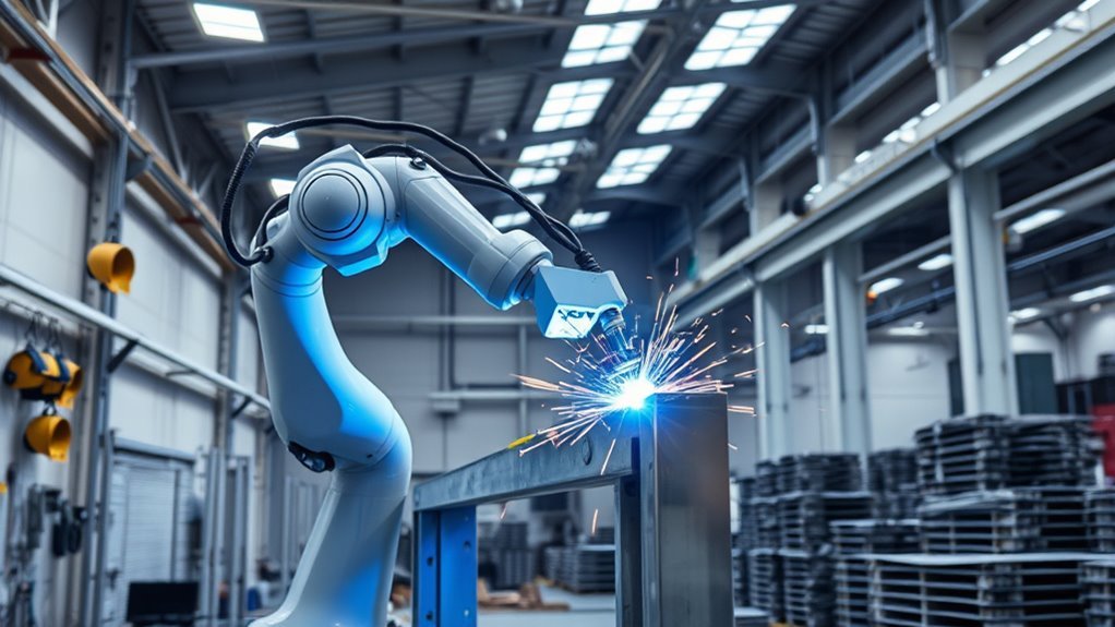
Robotic welding is an automated manufacturing process in which an industrial robot performs programmed welding motions with repeatable position, orientation, and travel.
The robot works as part of a larger system rather than as a stand-alone welder. The American Welding Society’s D16.2 guide describes typical robotic and automatic arc-welding installations as including the manipulator, power source, welding torch, electrode or wire-delivery equipment, shielding-gas delivery, welding circuit, control and communication equipment, and grounding system. Cells may also use safety devices, joint tracking, vision, fixtures, and positioners.
Robots can be used with several joining processes. Common examples include gas metal arc welding (GMAW/MIG), gas tungsten arc welding (GTAW/TIG), flux cored arc welding (FCAW), plasma arc welding (PAW), resistance spot welding, and laser welding. The best process depends on the material, thickness, joint design, quality requirements, access, and production rate.
Compared with manual welding, automation can increase the percentage of production time spent welding because the programmed motion is repeatable and the robot does not experience operator fatigue. However, there is no single arc-on-time percentage that applies to every automated cell. Loading, unloading, tack welding, fixture design, cleaning, inspection, consumable changes, maintenance, and changeovers can all limit utilization.
Industrial adoption also continues to evolve. The Association for Advancing Automation reported that North American companies ordered 36,766 robots in 2025. That figure covers industrial robotics broadly rather than welding robots alone, but it shows the continuing investment in automation across manufacturing.
Preliminary International Federation of Robotics data reported 38,000 industrial robot installations in the United States in 2025, an 11% increase from 2024. The figure covers industrial robots generally, not welding robots specifically.
How Robotic Welding Systems Work
A robotic welding system coordinates robot motion with the welding process. The workpiece is first located in a fixture or positioner so the joint appears where the robot program expects it to be.
The operator or programmer establishes the weld path and process settings. Depending on the system, this may be done with a teach pendant, direct teaching on a collaborative robot, offline programming software, or a combination of methods. The controller then coordinates travel speed, torch angle, weld start and stop points, weaving or multi-pass motion, positioner movement, and communication with the welding power source.
Some cells use sensing to compensate for normal part variation. For example, touch sensing can locate a joint before welding, while through-arc seam tracking or optical sensors can adjust the path during suitable welding applications. FANUC describes its Through Arc Seam Tracking system as using welding-current feedback to correct the robot’s vertical and lateral path when joint position changes.
Offline programming can reduce the amount of production time used for teaching new paths, especially for larger or more complex programs. It does not eliminate commissioning: the real cell still needs verification of tooling, tool-center-point accuracy, part location, reach, clearances, welding parameters, and safety functions.
Pro Tip: Before optimizing robot speed, stabilize the part. A fast robot cannot compensate for inconsistent joint gaps, changing tack locations, warped components, or fixtures that locate the workpiece differently from cycle to cycle.
Key Components of a Robotic Welding Cell
A robotic welding cell combines motion, welding equipment, workholding, controls, and safeguarding. The exact configuration varies by application, but a typical system may include:
- Industrial robot or cobot: Moves the torch, gun, sensor, or sometimes the workpiece.
- Robot controller: Stores programs and coordinates robot motion, I/O, positioners, and welding commands.
- Welding power source: Produces and controls the electrical output required by the process.
- Torch or welding gun: Delivers the arc, electrode, shielding gas, or spot-welding force at the joint.
- Wire or electrode delivery: Feeds filler metal when the selected process requires it.
- Shielding-gas system: Supplies and regulates gas for processes such as GMAW and GTAW.
- Fixtures: Locate and clamp components so the joint is repeatable.
- Positioners or external axes: Rotate or reposition a part to improve weld access and orientation.
- Sensors: May provide touch sensing, seam tracking, vision, part detection, or process monitoring.
- Safety equipment: May include perimeter guarding, interlocked gates, presence-sensing devices, emergency stops, appropriate welding screens, and other safeguards selected through risk assessment.
- Peripheral equipment: Torch cleaners, wire cutters, TCP-check stations, fume extraction, coolant equipment, and inspection systems may also be required.
A cell performs well only when these components are engineered as one system. Poor workholding, unreliable wire delivery, inadequate torch access, or a badly planned load station can limit output even when the robot itself is highly repeatable.
Which Robotic Welding Processes to Automate?
Manufacturers normally automate welding applications where the joint geometry, production demand, part presentation, and process requirements can be controlled consistently.
GMAW/MIG is widely suited to robotic welding because filler wire is continuously fed and the process supports productive welding on many steels, stainless steels, and aluminum applications.
GTAW/TIG can be automated where precise heat input, clean appearance, thin material, or specialized alloys justify the slower and more sensitive process.
FCAW can also be automated for suitable fabrication work. PAW is another process covered by AWS guidance for robotic and automatic arc-welding installations.
Laser welding can deliver narrow, concentrated welds and high processing speeds, but joint fit-up, shielding, optics, laser safety, material behavior, and capital cost require careful engineering.
Resistance spot welding is especially important for sheet-metal production, including automotive manufacturing. It uses a different process architecture from robotic arc welding and has its own equipment and safeguarding requirements.
| Process | Typical Strength | Key Automation Consideration |
|---|---|---|
| GMAW / MIG | Productive continuous-wire arc welding | Wire delivery, torch access, spatter control, joint repeatability |
| GTAW / TIG | Precision and clean welds | Tight fit-up, electrode condition, heat control |
| FCAW | High-deposition fabrication applications | Wire selection, fume control, slag/process requirements |
| Laser | Concentrated heat and potentially fast joining | Fit-up, beam safety, optics, shielding, process development |
| Resistance spot | High-volume sheet-metal joining | Gun access, electrode condition, force, current, guarding |
MIG Welding: Speed and Versatility
MIG welding, more formally GMAW, is a common choice for robotic arc welding because the continuous wire electrode integrates well with automated equipment. The process can provide productive deposition rates and repeatable starts when the wire-delivery system, torch, electrical contact, shielding gas, and parameters are stable.
Its versatility does not mean one program will suit every part. Material, thickness, joint design, transfer mode, shielding gas, wire diameter, torch angle, heat input, penetration requirements, and acceptance criteria must all be considered.
MIG Welding Speed
There is no single correct robotic MIG travel speed. The usable speed is established by the qualified or validated welding procedure and by the joint’s ability to meet fusion, penetration, bead-profile, dimensional, and defect requirements.
Increasing robot travel speed without considering the welding process can reduce heat input, change bead shape, create lack of fusion, or make the arc less tolerant of joint variation. Conversely, excessive heat input or slow travel can cause distortion, burn-through, excessive reinforcement, or other quality problems.
- Base travel speed on the welding procedure rather than robot capability alone.
- Verify wire-feed speed, voltage or arc length, current response, and shielding gas together.
- Check starts, stops, corners, gaps, and changes in torch orientation.
- Measure completed-part cycle time rather than quoting only inches per minute.
MIG Versatility Benefits
Robotic GMAW can be adapted to carbon steel, stainless steel, and aluminum when the power source, wire, liner, contact tip, drive system, gas, torch, and process settings are suitable for the material.
It also works with a wide range of joint types, part sizes, and production layouts. Positioners can present a weld in a more favorable orientation, while coordinated robot and positioner motion can improve access to complex assemblies.
The process can reduce variation caused by inconsistent manual torch movement, but only when upstream variation is controlled. Large joint gaps, inaccurate stamping or cutting, inconsistent tacks, distortion, contamination, and fixture wear can still create defects.
Robotic MIG Efficiency
Robotic MIG efficiency should be measured across the complete cell cycle, not only while the arc is on. A highly optimized program may still have poor throughput if operators spend too long loading the fixture or if the torch frequently stops for cleaning and recovery.
- Measure load and unload time.
- Measure robot positioning and welding time.
- Track fixture and positioner movement.
- Track tip changes, nozzle cleaning, wire faults, and recovery time.
- Track inspection, rework, and rejected parts.
- Monitor downtime separately from planned changeover and maintenance.
Automation can also reduce excess wire, shielding gas, grinding, and rework when process parameters are stable, but the savings should be measured from the plant’s actual baseline rather than assumed as a fixed percentage.
TIG and Laser Welding Applications
TIG welding (GTAW) and laser welding can both be automated for applications that demand precise control, but they solve different problems.
Robotic GTAW is useful for thin materials, controlled heat input, clean weld appearance, and specialized alloys. The process can be sensitive to fit-up, electrode condition, torch position, shielding, and contamination, so consistent part preparation matters.
Laser welding concentrates energy into a small area and can produce narrow welds with limited heat-affected width in suitable applications. Its actual speed and quality depend on laser type, power, optics, material, coating, joint design, gap, penetration requirement, shielding, and system integration.
Neither process should be selected only because it appears faster or more advanced. Manufacturers should run representative weld trials and verify mechanical properties, dimensional results, appearance, defect levels, and production cycle time before committing to a cell design.
Benefits of Robotic Welding Over Manual Welding
Compared with manual welding, robotic welding can offer several important advantages when the application is suitable for automation.
- Repeatable motion: The robot can reproduce programmed path, torch angle, travel speed, and position with high consistency.
- Stable cycle time: A properly functioning cell repeats a known sequence, making production planning easier.
- Higher potential utilization: Automation can reduce pauses caused by manual torch repositioning and operator fatigue.
- Reduced direct exposure: Guarded automation can separate workers from the arc, heat, spatter, and some repetitive welding tasks.
- Process-data capability: Modern systems may record alarms, program information, weld data, downtime, or inspection results.
- Lower rework potential: Stable parameters and repeatable part location can reduce variation when the underlying process is capable.
- Scalability: A validated process can be repeated across shifts or additional cells more predictably than a highly operator-dependent process.
Automation does not automatically guarantee good welds. The robot will repeat an incorrect path or unsuitable parameter just as consistently as it repeats a correct one. Welding engineering, part control, inspection, and maintenance remain essential.
Robotic Welding Safety and Risk Assessment
Robotic welding combines hazards from welding with hazards created by powered robot motion, positioners, clamps, tooling, and automated material handling.
The Occupational Safety and Health Administration notes that robot accidents often occur during non-routine conditions such as programming, maintenance, testing, setup, or adjustment, when a worker may be inside the robot’s operating envelope.
As of 2026, the American Welding Society lists D16.1M/D16.1:2026, Specification for Robotic Arc Welding Safety, as well as D16.3M/D16.3:2026, Risk Assessment Guide for Robotic Welding. Manufacturers and integrators should use applicable current standards and legal requirements when designing and validating a cell.
Warning: Never treat a robot’s normal automatic program as a safety device. Programming, troubleshooting, recovery, cleaning, maintenance, and fixture adjustment can place personnel closer to hazardous robot motion and welding energy. Safeguarding, hazardous-energy control, access procedures, training, and risk assessment should be designed and validated by qualified personnel.
Depending on the risk assessment and process, safeguards may include interlocked perimeter fencing, presence-sensing equipment, safe access points, emergency-stop systems, safe robot functions, welding screens, fume extraction, electrical protection, and procedures for servicing and hazardous-energy isolation.
Collaborative robots also require risk assessment. The word collaborative does not mean every welding application is safe for unrestricted human access. The welding arc, hot metal, sharp workpieces, fumes, positioners, tooling, and robot-mounted equipment can create hazards even when the robot itself supports collaborative safety functions.
How to Decide if a Part Is a Good Automation Candidate
Before pricing a robotic cell, evaluate the part and production process. The strongest candidates usually share several characteristics:
- Parts are produced repeatedly in meaningful quantities.
- Joint location is consistent from part to part.
- Fit-up and gap can be controlled.
- Components can be loaded into a reliable fixture.
- The robot can reach each joint with a practical torch angle.
- The welding process and procedure are stable.
- Upstream cutting, forming, machining, and tack welding are repeatable.
- The expected product life and demand justify the integration effort.
High-mix, low-volume work is not automatically unsuitable. Offline programming, flexible fixtures, vision, touch sensing, modular tooling, and easier robot interfaces have expanded the range of parts that can be automated. However, frequent changeovers can still reduce utilization and extend payback.
Robotic Welding Costs Explained
There is no dependable universal installed price for a robotic welding system. A simple pre-engineered cell and a custom multi-robot production line have very different cost structures.
| Cost factor | What it can include | Why it matters |
|---|---|---|
| Robot and controller | Robot, controller, pendant, software options | Defines reach, payload, motion capability, and programming environment |
| Welding package | Power source, torch, wire feeder, gas equipment, cooling | Must match the welding process and duty requirements |
| Fixtures and positioners | Clamps, locating tools, rotary tables, headstock/tailstock systems | Often determines repeatability and weld access |
| Safety system | Guarding, interlocks, scanners, stops, controls, welding screens | Required to control identified hazards |
| Integration | Engineering, PLC/HMI work, programming, wiring, commissioning | Can be a major part of a custom project’s cost |
| Facility work | Electrical service, gas, ventilation, foundations, floor space | May be excluded from the integrator’s cell quote |
| Training and validation | Operator, programmer, maintenance, welding and safety training | Affects startup performance and recovery from faults |
| Ongoing ownership | Consumables, spare parts, service, preventive maintenance, calibration, downtime | Should be included in ROI calculations |
Request quotes based on the same written scope so proposals can be compared fairly. Clarify whether each quote includes tooling, guarding, freight, installation, programming, procedure development, operator training, spare parts, extraction equipment, production validation, and support.
When Robotic Welding Is Worth the Investment
Robotic welding becomes easier to justify when the cell can produce enough acceptable parts to offset the capital, integration, training, maintenance, and operating costs.
A practical analysis starts with the plant’s existing process rather than generic industry percentages. Record:
- Annual part quantity.
- Manual cycle time per acceptable part.
- Actual welding time and handling time.
- Labor required per shift.
- Scrap and rework cost.
- Grinding and finishing time.
- Wire, gas, contact tips, nozzles, and other consumables.
- Downtime and maintenance.
- Floor-space and utility requirements.
- Expected automated cycle time.
- Expected cell availability and changeover time.
A simplified payback calculation is:
Simple payback period = total installed automation investment ÷ expected annual net savings.
Annual net savings should include realistic labor, throughput, scrap, rework, and consumable changes while subtracting additional maintenance, support, financing, utilities, and other recurring automation costs.
Note: A cell with a very fast welding program can still have a weak ROI if production volume is low, changeovers are long, fixtures are unreliable, or the robot frequently waits for parts. Evaluate good parts produced per shift, not robot motion speed alone.
How to Deploy a Robotic Welding Cell
A structured deployment reduces surprises during commissioning:
- Define the production target. Specify part families, annual volume, takt time, weld requirements, inspection criteria, shifts, and expected product life.
- Verify the welding process. Confirm that the joint can be welded consistently before automating it.
- Study part variation. Measure fit-up, gap, distortion, tack location, and dimensional variation.
- Design the fixture and material flow. Plan loading, unloading, locating, clamping, ergonomic access, and positioner movement.
- Perform the risk assessment. Identify robot-motion, welding, electrical, thermal, fume, pinch, crushing, and maintenance hazards.
- Select the robot and peripherals. Confirm reach, payload, torch clearance, positioner capacity, process equipment, sensing, and controller interfaces.
- Simulate or prove the cycle. Check reach, singularities, collision risk, cable routing, process time, and load/unload time.
- Integrate and commission the system. Program the cell, verify safety functions, establish TCP and frames, and tune the welding procedure.
- Validate production. Inspect representative parts and confirm weld quality, cycle time, repeatability, and recovery procedures.
- Train personnel. Operators, programmers, maintenance technicians, engineers, and safety personnel need role-appropriate training.
How to Future-Proof Your Welding Cell
A well-designed welding cell should allow reasonable changes in parts and production requirements without forcing a complete rebuild.
Modular fixtures, spare I/O capacity, accessible utilities, suitable robot reach, flexible positioners, and software options can make later changes easier. Offline programming can reduce some program-development downtime, while touch sensing, seam tracking, or vision may help a cell accommodate controlled part variation.
Future-proofing should not mean buying every option available. It means identifying likely changes—such as additional part families, larger components, new welding processes, inspection requirements, or increased output—and providing economical expansion paths where they make sense.
Maintenance planning is equally important. A robotic welding cell may require inspection or replacement of contact tips, nozzles, liners, torch components, cables, wire-delivery parts, positioner components, filters, coolant, safety devices, and other wear items. Robot and welding-equipment maintenance should follow the applicable manufacturer’s schedule.
Track recurring faults and downtime by cause. A cell that repeatedly loses time to wire-feed faults, dirty nozzles, fixture variation, sensor errors, or manual recovery may benefit more from fixing those bottlenecks than from increasing robot speed.
Frequently Asked Questions
What Are the Downsides of Robotic Welding?
The main disadvantages are capital and integration cost, fixture requirements, programming and maintenance needs, production disruption during commissioning, and reduced economic appeal when parts change frequently or volumes are low. Robots also do not eliminate quality control or safety responsibilities. Skilled personnel are still needed for welding engineering, programming, maintenance, troubleshooting, inspection, and system supervision.
How Much Do Robotic Welders Cost?
There is no single reliable price for a robotic welding system. The installed cost depends on the robot, welding equipment, fixtures, positioners, sensing, safety equipment, controls, integration, facility work, programming, training, validation, and support. Compare quotations using the same written scope and calculate total installed and operating cost rather than relying on a generic price range.
Is Robotic Welding Worth It?
Robotic welding can be worth the investment when parts are repeatable, demand is sufficient, the welding procedure is stable, and the automated cell reduces the cost per acceptable part. The decision should be based on measured cycle time, labor, scrap, rework, consumables, uptime, maintenance, changeover, and installed cost rather than a universal payback claim.
How Much Faster Is a Robotic Welder Than a Human Welder?
There is no dependable universal speed multiplier. A robot may reduce non-welding motion and repeat a cycle consistently, but allowable welding travel speed is limited by the process and weld-quality requirements. Compare total time per acceptable part, including loading, positioning, welding, cleaning, inspection, changeover, and downtime.
What Parts Are Best for Robotic Welding?
Good candidates have repeatable geometry, controlled joint gaps, consistent tack locations, reliable fixtures, adequate torch access, a stable welding procedure, and enough recurring production to justify setup and integration. High-mix work can also be automated, but fixture changes and programming time must be included in the economics.
What Safety Standards Apply to Robotic Welding?
Applicable requirements depend on location and system design. In the United States, OSHA provides robotics and welding safety requirements and guidance. The American Welding Society publishes robotic-welding documents including D16.1 for robotic arc-welding safety and D16.3 for robotic-welding risk assessment. Integrators should also evaluate applicable robot, machinery, electrical, welding, and hazardous-energy requirements for the specific installation.
Conclusion
Robotic welding can improve throughput, repeatability, process consistency, and worker separation from hazardous welding tasks, but the robot itself is only one part of a successful system. Part design, fit-up, fixtures, welding procedures, loading strategy, positioners, sensing, safeguarding, inspection, maintenance, and trained personnel all influence the result.
The strongest projects begin with real production data. Measure current cycle time, labor, scrap, rework, consumables, downtime, and part variation; then compare those numbers with a proposed automated cycle and total installed cost. That approach provides a much more reliable answer than generic claims about robot speed, arc-on percentage, cost, or payback.
Sources
- American Welding Society — Robotic Welding Standards — current AWS robotic-welding safety, risk-assessment, component, training, and qualification documents.
- AWS D16.2M/D16.2:2021 — components and design considerations for robotic and automatic arc-welding installations.
- OSHA Robotics Overview — robot hazards, non-routine operating risks, safeguarding, and worker safety context.
- Association for Advancing Automation — 2025 North American Robot Orders — current regional robotics market data published in 2026.
- International Federation of Robotics — 2025 U.S. Robot Installations — preliminary 2026 release covering U.S. industrial robot installations in 2025.
- FANUC Through Arc Seam Tracking — example of robotic arc-welding seam-tracking technology.