MIG welding gas pressure is best set by controlling shielding-gas flow, not by choosing a fixed PSI number. For most gas-shielded MIG work, you should read the flow in CFH or liters per minute while gas is actually moving through the gun. The correct setting then depends on the process, gas, wire, nozzle, joint, and air movement.
Quick Answer
Do not set MIG shielding by cylinder pressure alone. A common manufacturer starting range is about 20–35 CFH for many shop MIG setups, while aluminum with 100% argon commonly uses 20–30 CFH. Set the flow while gas is running, then adjust only enough to maintain clean, porosity-free shielding.
Key Takeaways
- CFH or L/min, rather than a fixed PSI value, is the useful setting for MIG shielding gas.
- Manufacturer guidance varies: Miller lists 20 CFH for light-duty MIG and 25–35 CFH for short-circuit MIG.
- Aluminum MIG with 100% argon commonly uses 20–30 CFH rather than automatically requiring 30–50 CFH.
- Wind should be controlled with a screen or enclosure instead of simply turning the gas flow much higher.
- Too little gas and too much turbulent gas can both lead to porosity, so troubleshoot the entire gas path before increasing CFH.
What Is the Right MIG Gas Flow Rate?
)
The right MIG gas flow rate is the lowest flow that keeps the weld pool fully shielded without creating turbulence. There is no single correct CFH setting for every welder, because the machine, transfer mode, gas, nozzle, wire, joint, and surrounding airflow all change the amount of gas you need.
Miller’s MIG beginner guidance gives 20 CFH as a good starting point for light-duty welding. Its more detailed shielding-gas guidance recommends 25–35 CFH for short-circuit MIG.
That difference is important. A small hobby machine doing light work in still air may need less shielding gas than a higher-output setup, a larger joint, or a procedure using a different transfer mode.
| Application | Verified Starting Guidance | Important Detail |
|---|---|---|
| Light-duty MIG | About 20 CFH | Miller general starting point |
| Short-circuit MIG | 25–35 CFH | Adjust for gun, joint, and airflow |
| Aluminum MIG, 100% argon | 20–30 CFH | Miller aluminum guidance |
| Lincoln SuperArc L-56 | 30–50 CFH | Product-specific manufacturer range |
Use those values as starting points, not universal limits. The chart inside your welder, the wire data sheet, or a qualified welding procedure should take priority when it gives a specific flow range.
A suitable 75/25 argon/CO2 blend is a common choice for mild-steel MIG because gas composition also affects arc behavior, spatter, and bead shape.
Set MIG Gas Flow by Gas Type
The shielding gas changes both weld behavior and the flow range that works well. Start with the recommendation for your exact wire and machine instead of assuming that one CFH setting fits argon, CO2, helium blends, and stainless mixtures equally.
For mild steel, common gases include 75% argon/25% CO2 and 100% CO2. Miller’s shielding-gas guidance recommends 25–35 CFH for short-circuit MIG and notes that other transfer modes may run somewhat higher.
Stainless steel uses several shielding mixtures depending on the machine and transfer mode. These include helium-based trimixes and low-CO2 argon blends, so the correct flow should come from the machine or consumable procedure rather than from a generic stainless-steel number.
For aluminum, 100% argon is the standard gas for most MIG work. Helium/argon mixtures are also used on heavier sections when additional arc energy is needed.
Choosing the correct machine and process controls also matters. A suitable MIG welder setup should let you control wire feed, voltage, and shielding gas consistently rather than treating gas flow as an isolated setting.
Match CFH to Metal and Wire Size
Base metal matters, but wire diameter and welding procedure matter too. Larger wire and higher-deposition procedures can require a different gas setting because the arc, puddle size, nozzle arrangement, and transfer mode change together.
Mild Steel CFH Ranges
For mild-steel MIG, a practical manufacturer-backed range often begins around 20–35 CFH for light-duty and short-circuit work. Do not treat the old 10–15 CFH figure as a universal indoor recommendation.
Miller gives 20 CFH as a light-duty starting point and 25–35 CFH for short-circuit MIG. Lincoln’s guidance can be higher for particular consumables and procedures, which shows why the wire data sheet matters.
If a weld develops porosity, increasing flow is only one possible fix. First check the nozzle, diffuser, hose connections, gun seating, contact-tip-to-work distance, surface cleanliness, and drafts.
Stainless and Aluminum Flow
Stainless and aluminum require the correct shielding-gas chemistry as well as enough flow. A flow number without the matching gas type and transfer mode can be misleading.
A current Miller Multimatic 215 parameter chart specifies 25–35 CFH for its stainless-steel MIG setup using 308L wire and 98% argon/2% CO2. That is a machine-specific value rather than a universal stainless rule.
For aluminum MIG with 100% argon, Miller recommends 20–30 CFH. This corrects the idea that ordinary aluminum MIG automatically requires 30–50 CFH.
Higher flow can still be appropriate for larger nozzles or helium-containing aluminum procedures. Lincoln notes that aluminum GMAW shielding flows can rise substantially when wide nozzles and high-helium blends are used.
Wire Size Flow Adjustments
Wire diameter gives you another useful starting point, but manufacturer formulas are only rules of thumb. They still need adjustment for gas type, joint geometry, nozzle, transfer mode, and air movement.
Lorch’s MIG/MAG guidance uses wire-diameter formulas for setting flow while the gas is running. Its MIG rule is wire diameter in millimeters multiplied by 13.5 for liters per minute, while its MAG rule uses 11.5.
- Use the machine or wire manufacturer’s chart first when one is available.
- Set the flow while gas is moving through the system.
- Expect wire size, arc type, nozzle size, and joint shape to affect the final setting.
- Do not increase CFH automatically just because you move to a thicker wire.
- Recheck gas coverage whenever you change the gun, nozzle, wire, or transfer mode.
This is especially useful on a multi-process welder, because gas requirements can change when you switch processes or consumables.
Lincoln’s SuperArc L-56 specification, for example, lists a shielding-gas flow range of 30–50 CFH. The original 35-CFH starting and 50-CFH maximum wording was therefore too narrow.
Adjust for Nozzle Size and Weld Position
Nozzle diameter and gun position affect how the shielding-gas envelope reaches the puddle. Larger nozzles can require more volume, while excessive distance from the work lets the gas disperse before it reaches the molten metal.
There is no dependable universal rule that a 3/8-inch nozzle must never exceed 30 CFH or a 1/2-inch nozzle must never exceed 40 CFH. Manufacturer guidance instead treats nozzle diameter as one of several variables that determine the final flow.
Lincoln states that gun angle, nozzle diameter, joint configuration, and wind conditions can all change shielding demand. Miller likewise warns that excessive contact-tip-to-work distance can weaken gas coverage.
Out-of-position welding may also need adjustment because the gun angle and joint geometry change the way gas surrounds the puddle. Use your procedure as the starting point, then confirm that the actual weld remains properly shielded.
If you are learning these controls, a welder with clear adjustments can make setup easier; this guide to beginner welding machines covers common process options.
Dial In MIG Gas Flow Indoors and Outdoors
Still indoor air makes gas-shielded MIG much easier to control. Outdoors, moving air can strip the shielding envelope away faster than simply increasing CFH can replace it.
Indoor Flow Ranges
For indoor welding, start with the value specified by your welder or consumable manufacturer. In the absence of a more specific procedure, current Miller guidance places common light-duty and short-circuit MIG starting points around 20–35 CFH.
- Light-duty MIG: about 20 CFH is a documented Miller starting point.
- Short-circuit MIG: Miller recommends 25–35 CFH.
- Aluminum MIG with pure argon: Miller recommends 20–30 CFH.
- Lincoln SuperArc L-56: Lincoln specifies 30–50 CFH.
These ranges overlap because they describe different equipment and procedures. That is why a single “correct MIG pressure” number cannot cover every machine.
Outdoor Draft Adjustments
For outdoor MIG, control the wind before you increase gas flow. A higher CFH setting cannot reliably compensate for a strong crosswind that blows the shielding gas away from the puddle.
Miller recommends using a wind block or tent around gas-shielded outdoor welding. If you cannot protect the weld zone from moving air, a process that does not depend on externally supplied shielding gas may be more practical.
Warning: Do not confuse shielding-gas protection with ventilation. Welding still requires suitable fume control, and shielding gases can contribute to oxygen-deficiency hazards in confined areas.
Higher-output machines can also have operating limits unrelated to gas flow. If you are comparing equipment, review its duty-cycle limits separately from shielding-gas settings.
Nozzle Size Limits
Nozzle size affects gas velocity and coverage area, but there is no universal CFH maximum tied to each nozzle diameter. The correct limit depends on the entire torch and welding procedure.
- A smaller nozzle generally needs less total gas volume.
- A larger nozzle can support a broader gas envelope and may require more flow.
- Spatter inside the nozzle can disturb otherwise adequate gas flow.
- Excessive nozzle-to-work distance can let the gas shield disperse.
- Increasing gas until the flow becomes turbulent can make porosity worse.
Use nozzle size as an adjustment factor, not as a stand-alone setting chart.
Fix Porosity, Turbulence, and Poor Shielding
If a MIG weld is porous, do not immediately turn the gas higher. Porosity can come from low flow, excessive turbulent flow, drafts, leaks, contamination, excessive gun distance, or blocked consumables.
- Confirm gas is reaching the gun. Check the cylinder valve, regulator, hose, gas connection, and gun seating.
- Set flow with gas running. Use the trigger, purge function, or gas-test function recommended for your welder.
- Inspect the nozzle and diffuser. Remove heavy spatter that can distort the shielding pattern.
- Check the gun distance. Moving too far from the work reduces effective coverage at the puddle.
- Look for drafts. Close doors, redirect fans, or install a wind screen before raising flow.
- Check the metal. Oil, moisture, paint, oxide, and other contamination can also create porosity.
- Adjust CFH gradually. If everything else is correct, make small changes within the procedure or manufacturer range.
Pro Tip: If the regulator shows the expected CFH but porosity continues, check gas flow at the end of the MIG gun with a suitable external flow tester. This can reveal leaks or restrictions between the regulator and nozzle.
Arc instability and spatter can accompany poor shielding, but they are not proof of a gas problem by themselves. Wire feed, voltage, polarity, contact-tip condition, and work connection can produce similar symptoms.
The machine’s process and duty-cycle capabilities should therefore be checked separately when troubleshooting performance.
Fine-Tune CFH With a Flowmeter
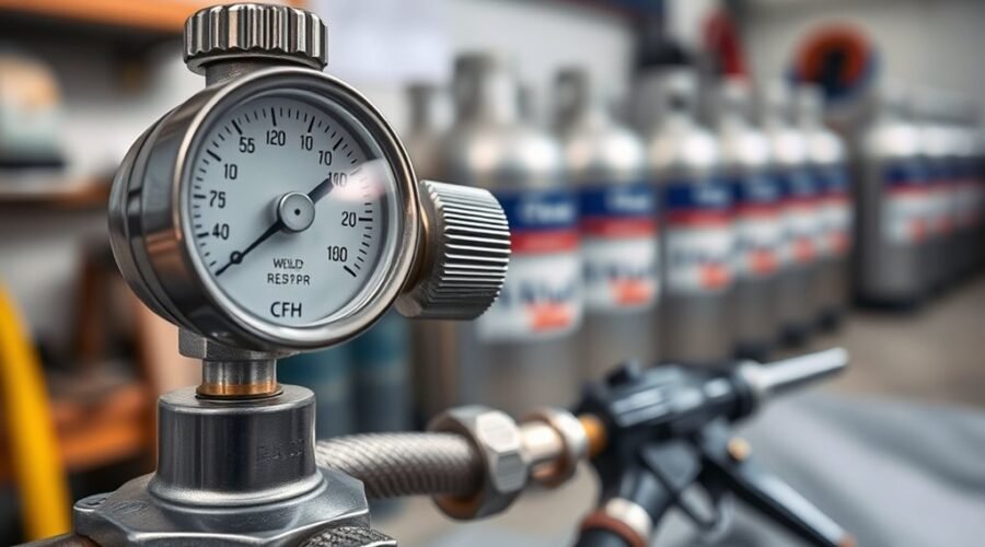
A flowmeter helps you set shielding gas in CFH or L/min while gas is actually moving. This is more useful for MIG shielding than trying to choose a fixed delivery-pressure number in PSI.
A cylinder gauge tells you cylinder pressure. A welding flowmeter or flow gauge is designed to indicate the gas flow delivered to the welding system. On a ball-type flowmeter, read the device according to its manufacturer’s instructions; Lincoln specifies reading the middle of the ball on its LN-25 Pro Dual Power flowmeter.
- Open the shielding-gas cylinder as instructed for your regulator and gas system.
- Activate the machine’s gas purge, gas-test function, or trigger so gas is flowing.
- Set the flowmeter to the procedure or manufacturer starting value.
- Release the gas control and make a test weld on suitable scrap.
- Inspect for porosity and confirm the gas path is free of leaks, blockages, and drafts.
- Adjust only as needed rather than assuming more CFH provides more protection.
Efficient flow reduces wasted cylinder gas, but gas economy should never come at the expense of proper shielding. If you also use stick welding when gas-shielded MIG is unsuitable, this guide to general-purpose welding rods covers common electrode choices.
Note: For structural, code-controlled, or production welding, follow the qualified welding procedure rather than a general CFH chart. A welding supervisor, inspector, or welding engineer can confirm the required procedure variables.
OSHA’s welding requirements also emphasize adequate ventilation, especially in confined spaces. Shielding gas protects the weld pool; it is not a substitute for ventilation or fume control.
Frequently Asked Questions
What Is the Proper Gas Flow Setting for MIG Welding?
A common starting range for many MIG setups is about 20–35 CFH, but the correct setting comes from your machine, wire, and procedure. Miller lists 20 CFH for light-duty MIG and 25–35 CFH for short-circuit MIG, while specific consumables may require different values.
What Is the Recommended Gas Pressure for MIG Welding?
There is no universal MIG shielding-gas pressure in PSI that replaces a flow setting. Set the shielding gas by CFH or L/min while gas is flowing, and use the regulator or flowmeter designed for your gas and welding system.
What Happens if Gas Flow Is Too High in MIG Welding?
Gas flow that is too high can waste shielding gas and create turbulence that draws surrounding air into the shielding envelope. The result can be porosity even though the flowmeter shows more gas, so higher CFH does not always mean better protection.
What Should My Flow Meter Be Set at for MIG Welding?
Set the flowmeter to the value recommended for your machine, wire, gas, and procedure while gas is actually flowing. If no more specific value is available, manufacturer guidance around 20–35 CFH covers many common light-duty and short-circuit MIG applications.
Can I MIG Weld Outdoors by Turning the Gas Flow Higher?
Increasing gas flow alone is not a reliable fix for outdoor wind. Use a wind block or enclosure to protect the weld zone, because strong airflow can blow shielding gas away even when the flowmeter is set higher.
How Do I Know if Enough Shielding Gas Reaches the MIG Gun?
Check the flow while gas is running, inspect the nozzle and diffuser, and make sure the hose and gun connections do not leak. If the regulator reading looks correct but porosity remains, an external flow tester at the gun can confirm what actually reaches the nozzle.
Conclusion
Correct MIG welding gas pressure is really a question of controlled gas flow. Start with the flow recommended for your machine, wire, and gas, measure it while gas is moving, and adjust for nozzle, joint, transfer mode, and airflow.
A clean gas path and protected weld zone matter as much as the CFH number. If porosity appears, check for leaks, blocked consumables, excessive gun distance, contamination, and drafts before simply increasing the flow.
Sources
- Miller Electric — MIG Welding Tips and Techniques for Beginners: 20 CFH light-duty starting guidance and MIG setup fundamentals.
- Miller Electric — MIG Shielding Gas Guidance: 25–35 CFH short-circuit range, turbulence warning, wind blocks, and gas-selection guidance.
- Miller Electric — How to Successfully MIG Weld Aluminum: 100% argon and 20–30 CFH aluminum MIG guidance.
- Miller Electric — Multimatic 215 PRO Parameter Chart: stainless-steel MIG shielding-gas flow example.
- Lincoln Electric — SuperArc L-56 Specification: shielding gases and 30–50 CFH product flow range.
- Lorch — Setting the Gas Flow Rate for MIG/MAG Welding: wire-diameter flow formulas and flowmeter setup.
- OSHA — Welding, Cutting, and Brazing Requirements: welding ventilation and confined-space precautions.