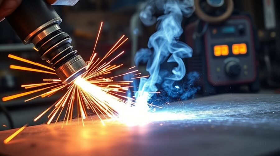
Flux core welding is a productive wire-fed welding process that can handle fabrication, repair, construction, and outdoor work when the correct electrode and technique are used. The most important beginner lesson is that there is no single voltage, wire-feed speed, polarity, or stickout that fits every flux-cored wire. Start with the machine chart and electrode data sheet, make a test weld on matching scrap, and adjust from there.
Quick Answer
Flux core welding uses a continuously fed tubular wire containing flux. Self-shielded FCAW needs no external shielding gas, while gas-shielded FCAW uses a specified gas. For good welds, use the wire manufacturer’s polarity and parameter range, maintain the specified stickout, drag the gun steadily, clean the joint, remove slag between passes, and test settings on scrap first.
Key Takeaways
- Flux Cored Arc Welding, or FCAW, uses a continuously fed tubular electrode filled with flux.
- FCAW-S is self-shielded and does not need an external gas cylinder; FCAW-G uses shielding gas specified for the electrode.
- Do not rely on one universal voltage, wire speed, stickout, polarity, or gas setting. Use the welder chart and wire data sheet.
- A drag technique with a modest travel angle is normally preferred because flux-cored welds produce slag.
- Clean material, stable wire feeding, proper ventilation, correct PPE, and test welds help prevent porosity, spatter, lack of fusion, and other problems.
At a Glance
| Time Required | About 10–20 minutes for inspection, setup, and a test weld; actual welding time depends on the joint. |
| Difficulty | Beginner to intermediate; structural or code work requires approved procedures and appropriate qualification. |
| Tools Needed | FCAW-capable welder, correct flux-cored wire, work clamp, correct drive roll and contact tip, welding helmet, gloves, protective clothing, chipping hammer, wire brush, and suitable ventilation. |
| Cost | Varies by welder, wire, PPE, and consumables. FCAW-S does not require a shielding-gas cylinder. |
What Is Flux Core Welding?
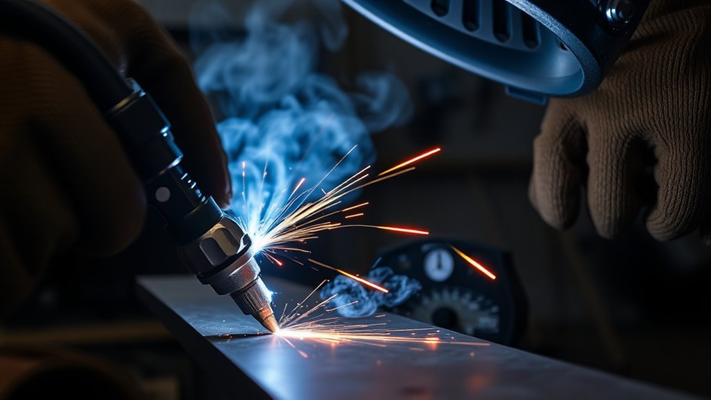
Flux core welding, formally called Flux Cored Arc Welding (FCAW), is an arc-welding process that uses a continuously fed tubular wire electrode containing flux. The electrode supplies filler metal while the flux helps protect and condition the molten weld pool. The American Welding Society recognizes self-shielded and gas-shielded forms of the process.
In self-shielded FCAW (FCAW-S), ingredients inside the electrode provide the shielding system, so no external shielding-gas cylinder is required. This portability makes FCAW-S useful for field work and many outdoor applications.
In gas-shielded FCAW (FCAW-G), the flux-filled electrode is used with an external shielding gas specified for that particular wire. FCAW-G is widely used in fabrication and heavy welding because suitable electrodes can provide high deposition rates and stable operation.
The defining feature of FCAW is the tubular flux-cored electrode. Whether external shielding gas is required depends on the electrode classification and manufacturer.
Flux-cored wires are available for carbon steel, low-alloy steel, stainless steel, and specialized applications. The usable material thickness is not defined by a universal “20 gauge and above” rule; it depends on the wire diameter, electrode classification, machine output, joint design, position, and welding procedure.
FCAW is valued for productive deposition rates and, with appropriate self-shielded electrodes, portability outdoors. However, the process produces slag that must be removed and can generate substantial welding fumes, so ventilation and personal protection are essential.
How Flux Core Welding Works
When the trigger is pressed, the machine continuously feeds the tubular electrode toward the workpiece. An electric arc forms between the electrode and the base metal, melting both the wire and the joint surface. The flux ingredients react in the arc and weld pool, helping provide shielding, deoxidation, slag formation, and other functions determined by the electrode formulation.
| Part of the Process | What It Does | Why It Matters |
|---|---|---|
| FCAW-S | Uses a self-shielded electrode | No external shielding gas is required |
| FCAW-G | Uses a flux-cored electrode plus external gas | Supports wire-specific fabrication and structural applications |
| Electric arc | Generates welding heat | Melts the electrode and base metal |
| Consumable wire | Continuously supplies filler metal | Supports high deposition rates |
| Flux and slag | Help protect and condition the weld | Slag must normally be removed after welding and between passes |
| Travel speed | Controls heat input and bead shape | Too fast or too slow can contribute to weld defects |
Stable wire feeding, correct electrical parameters, suitable travel speed, proper gun position, and the specified electrode extension all work together. No single parameter should be adjusted in isolation without watching how the arc and weld bead respond.
FCAW-S vs FCAW-G: Which Should You Use?
| Feature | FCAW-S | FCAW-G |
|---|---|---|
| External shielding gas | No | Yes |
| Outdoor portability | Generally very good | Wind can disturb external shielding gas |
| Typical use | Field repair, construction, portable welding | Shop fabrication, structural and production welding |
| Polarity | Depends on electrode; many popular E71T-11/T-8 wires use DCEN | Depends on electrode; many common T-1 wires use DCEP |
| Shielding selection | Built into electrode system | Use only the gas approved for the electrode |
Do not select polarity or shielding gas from this comparison alone. The exact electrode data sheet is the final authority. Hobart notes that while many common self-shielded wires use DCEN, other self-shielded and gas-shielded electrodes require DCEP.
Flux Core Welding Safety
Warning: Arc welding exposes you to intense ultraviolet and infrared radiation, hot metal, sparks, electricity, fire hazards, and welding fumes. Use a suitable welding helmet, safety glasses, gloves, flame-resistant clothing, adequate ventilation, and other protection required for the job. Never treat a small garage, tank, container, or other enclosed area as automatically safe for welding.
FCAW can produce significant fumes. OSHA guidance calls for suitable general or local exhaust ventilation where required to keep welding fumes within safe limits, especially in enclosed or confined locations. Review OSHA welding ventilation requirements and the AWS Z49.1 welding-safety resources before welding.
- Keep your head out of the fume plume and provide adequate ventilation or source extraction.
- Wear a welding helmet with an appropriate filter shade, safety glasses, welding gloves, and flame-resistant clothing.
- Inspect the gun, power cable, work lead, connectors, and insulation before use.
- Remove combustible materials and control sparks and hot slag.
- Identify paint, plating, galvanizing, stainless alloys, and other coatings or metals that can change fume hazards before heating them.
- Do not weld in a confined space without the required confined-space controls, atmospheric precautions, ventilation, and trained support.
- Follow the wire Safety Data Sheet, machine manual, workplace rules, and applicable welding procedure.
Flux Core Welding Settings for Beginners
The safest way to choose beginner flux core welding settings is to start with the wire manufacturer’s data sheet and the parameter chart on the welding machine. Voltage and wire-feed speed depend on electrode type, wire diameter, base-metal thickness, joint design, position, and machine.
That is why a blanket recommendation such as “20–30 volts and 200–400 inches per minute” can be misleading. Some small self-shielded wires operate well below that voltage range, while larger industrial gas-shielded wires may operate within or above it.
| Parameter | Better Beginner Starting Point |
|---|---|
| Voltage | Use the machine chart or electrode data sheet for the exact wire and material thickness. |
| Wire-feed speed | Start at the manufacturer’s recommended value, then fine-tune on matching scrap. |
| Polarity | Use exactly what is printed on the wire spool, data sheet, or electrode specification. |
| Stickout / CTWD | Follow the electrode recommendation. Roughly 1/2–3/4 inch is common for some small flux-cored wires, but it is not universal. |
| Travel angle | Use a drag technique with roughly 5–15 degrees of travel angle under normal conditions. |
| Travel speed | Adjust by bead shape, penetration, puddle control, and sidewall tie-in rather than using one universal inches-per-minute value. |
Miller’s flux-cored welding guidance recommends using the machine’s reference chart as a starting point and then refining the settings with test welds.
Pro Tip: Keep a piece of scrap with the same material, thickness, joint orientation, and surface condition beside the project. Make your parameter adjustment on the scrap first, then inspect the bead before welding the actual part.
Choose the Right Wire, Polarity, and Gas
Wire selection, polarity, and shielding method determine how a flux-cored system operates. Match the filler metal to the base metal, required mechanical properties, welding position, machine output, and service requirements.
For general mild-steel hobby and repair work, 0.030-inch and 0.035-inch self-shielded wires are common. A 0.030-inch wire offers good versatility on lighter material, while a 0.035-inch wire can provide more deposition for heavier work if the machine supports it. Larger wire sizes are used as machine capacity and application demands increase.
The electrode classification matters more than diameter alone. A common E71T-11 wire, for example, is a self-shielded carbon-steel electrode that is widely used for general-purpose welding. Other FCAW classifications are designed for different positions, shielding gases, toughness requirements, or applications.
Note: Never assume that every self-shielded electrode is DCEN or every gas-shielded electrode is DCEP. Hobart’s filler-metal guidance specifically recommends checking the product data sheet because polarity varies by wire.
FCAW-G shielding gas is also electrode-specific. Depending on its classification, a gas-shielded flux-cored wire may be designed for 100% CO2, a mixture such as 75% argon/25% CO2, or more than one approved gas. The gas can change arc behavior and deposited weld-metal properties, so use only the gas listed by the manufacturer.
How to Set Up a Flux Core Welder
- Identify the electrode. Confirm its classification, diameter, recommended base metal, welding positions, polarity, shielding requirements, CTWD, and parameter range.
- Inspect the machine and cables. Check the gun, work lead, connectors, cable insulation, contact tip, and liner for damage or excessive wear.
- Install the correct drive roll. Flux-cored wire is softer than solid MIG wire, so equipment commonly uses the appropriate knurled or flux-core drive-roll groove specified by the machine manufacturer.
- Load the wire correctly. Confirm spool orientation and route the wire through the drive system without crushing or deforming it.
- Adjust drive-roll pressure. Use enough tension for consistent feeding but not so much that the tubular electrode is flattened.
- Set electrode polarity. Connect the gun and work lead exactly as required for the wire.
- Connect shielding gas if using FCAW-G. Use the gas type and flow guidance specified for the electrode and equipment. FCAW-S requires no external shielding gas.
- Prepare and clamp the joint. Remove oil, moisture, heavy rust, paint, and loose scale from the weld area. Fit and tack the parts securely.
- Set voltage and wire-feed speed. Begin with the welder chart or wire data sheet for the material thickness and joint.
- Make a test weld. Weld matching scrap, inspect the bead, then change one parameter at a time if adjustment is needed.
Essential Flux Core Welding Techniques
Once the machine is correctly configured, weld quality depends heavily on gun position, travel speed, stickout, joint fit-up, and control of the puddle.
Use a Drag Technique
Flux-cored welding normally uses a drag or pull technique: point the electrode back toward the weld pool and move away from the completed bead. A useful rule is that processes producing slag are generally dragged rather than pushed.
Keep the Travel Angle Modest
Under normal conditions, keep the travel angle around 5–15 degrees from perpendicular in the direction of travel. Miller notes that excessive travel angles above roughly 20–25 degrees can increase spatter, reduce penetration, and make the arc less stable.
Do not confuse travel angle with work angle. The correct work angle changes with the joint and welding position. A fillet weld, butt joint, horizontal weld, and vertical weld do not use exactly the same gun orientation.
Maintain the Correct Electrode Extension
Electrical stickout, often discussed with contact-tip-to-work distance, directly affects resistance heating and arc behavior. Instead of forcing every wire to a 3/8-inch stickout, use the range specified for the electrode. Many common small flux-cored wires use a longer extension than solid-wire MIG welding.
Control Travel Speed
Travel too quickly and the bead may become narrow with poor fusion or undercut. Move too slowly and the weld can become excessively wide or convex, increase heat input, and create poor bead shape. Watch the puddle and both toes of the weld rather than relying on one universal travel-speed number.
Joint Preparation, Tacking, and Multiple Passes
Flux-cored electrodes can be more tolerant of mill scale or surface contamination than some other wire processes, but that does not make joint preparation optional. Remove moisture, oil, paint, loose rust, and other contamination from the weld area. Materials with hazardous coatings require additional precautions before heating.
Fit the parts to the joint dimensions required for the job and use tack welds to maintain alignment. Poor fit-up can cause gaps, distortion, lack of fusion, and inconsistent bead shape.
After each weld pass, allow the joint to remain under control and remove slag before depositing the next pass. A chipping hammer and wire brush are commonly used. Welding over trapped slag can create slag inclusions and prevent proper fusion between passes.
For structural, pressure-containing, safety-critical, or code-controlled work, general internet settings are not a substitute for a qualified welding procedure specification, required inspection, or welder qualification.
Common Flux Core Welding Problems
Most flux core welding problems can be traced systematically to parameters, wire feeding, polarity, electrode extension, joint preparation, shielding, or technique.
| Problem | Likely Causes | What to Check |
|---|---|---|
| Excessive spatter | Incorrect voltage, wrong polarity, poor CTWD, unstable wire feeding, worn contact tip, contamination, or excessive gun angle | Confirm polarity first, return to the recommended parameter range, inspect consumables, and correct gun position. |
| Porosity | Oil, moisture, rust, paint, poor shielding, excessive wind, wrong gas, leaks, or unsuitable technique | Clean the joint, confirm the electrode and gas, check the gas system if FCAW-G, and protect the arc from excessive wind. |
| Lack of fusion | Insufficient heat input, excessive travel speed, poor work angle, heavy scale, poor joint preparation, or oversized weld pool | Verify parameters, slow or correct travel as needed, clean the joint, and make sure the arc reaches both joint faces. |
| Burnback | Wire feed too slow for the voltage, contact tip too close to the work, feeding restriction, or incorrect setup | Check WFS, CTWD, tip condition, liner, drive rolls, and spool tension. |
| Birdnesting or erratic feeding | Excessive drive-roll pressure, wrong drive roll, liner restriction, damaged tip, or tangled wire | Correct the wire path and tension and replace damaged consumables. |
| Slag inclusion | Slag left between passes, poor joint access, low heat input, or bad technique | Clean every pass thoroughly and ensure adequate fusion before adding the next bead. |
Spatter deserves special attention because it is often blamed only on high voltage. In reality, Miller’s troubleshooting guidance notes that low voltage can also increase spatter with flux-cored wire, along with incorrect polarity and consumable problems.
Flux Core Welding Tips for Better Results
Begin every unfamiliar setup with a test weld on scrap metal that matches the project as closely as possible. This allows voltage, wire-feed speed, travel speed, and technique to be evaluated without risking the finished part.
Keep the wire manufacturer’s recommended electrode extension rather than forcing a generic 3/8-inch stickout. Maintain a steady drag angle and watch the leading edge and sides of the weld pool so both toes tie into the base metal.
Keep the base metal and wire dry and reasonably clean. Even when a particular flux-cored electrode is designed to tolerate some mill scale or surface contamination, removing oil, moisture, loose rust, paint, and debris improves consistency.
Listen to the arc and watch the bead. An erratic arc, repeated popping, changing wire speed, or inconsistent bead can indicate a feeding problem rather than simply a voltage problem.
Remove slag after the weld cools enough to handle safely and before placing another pass over it. Inspect the bead for obvious porosity, undercut, poor toe fusion, cracks, or trapped slag.
Self-shielded flux core welding does not need a gas cylinder, which makes it useful for portable work. Gas-shielded FCAW can provide excellent results in controlled shop conditions, but the wire’s specified gas and procedure must be followed.
Frequently Asked Questions
What Is the Best Setting for Flux Core Welding?
There is no single best flux core welding setting. Start with the voltage, wire-feed speed, polarity, shielding gas, and CTWD specified by the welder chart and the exact wire manufacturer’s data sheet. Material thickness, wire diameter, welding position, and joint design all affect the correct settings. Make a test weld on matching scrap before welding the project.
What Are Some Tips and Tricks for Flux Core Welding?
Confirm polarity before welding, clean the joint, use the recommended stickout, keep a steady drag angle, set voltage and wire-feed speed from the machine or wire chart, make a scrap test, watch both edges of the puddle, and remove slag between passes. Also inspect drive rolls, the contact tip, liner, cables, and wire if the arc becomes unstable.
Is It Better to Push or Pull When Flux Core Welding?
A pull or drag technique is generally preferred for flux-cored welding because the process produces slag. Under normal conditions, keep a modest travel angle of roughly 5–15 degrees. The correct work angle still depends on whether you are making a fillet, butt, horizontal, vertical, or other joint.
Why Do I Get a Lot of Spatter When Flux Core Welding?
Excessive spatter can come from incorrect voltage, wrong polarity, unsuitable stickout, excessive gun angle, dirty metal, worn contact tips, or unstable wire feeding. Do not assume voltage is too high; low voltage can also increase spatter on some flux-cored setups. Return to the manufacturer’s parameter range and check one variable at a time.
Does Flux Core Welding Need Shielding Gas?
It depends on the electrode. FCAW-S wire is self-shielded and does not require external gas. FCAW-G wire requires an external shielding gas such as an approved CO2 or argon/CO2 mixture. Use only the gas listed for the specific wire.
What Polarity Should I Use for Flux Core Welding?
Use the polarity printed on the wire spool or product data sheet. Many common E71T-11 self-shielded wires use DCEN, while many gas-shielded T-1 wires use DCEP, but those patterns are not universal. Incorrect polarity can cause unstable operation, excessive spatter, and poor weld quality.
Conclusion
Flux core welding is a practical process for repair, fabrication, construction, and field work because it combines continuous wire feeding with a flux-cored electrode. Self-shielded FCAW adds portability because it does not need an external gas cylinder, while gas-shielded FCAW supports many productive shop and structural applications.
The key to reliable results is not memorizing one voltage or wire-speed number. Identify the exact wire, use its required polarity and shielding method, begin with the manufacturer’s parameter range, maintain the recommended electrode extension, use a steady drag technique, remove slag between passes, and test the setup on scrap. Combined with proper PPE and ventilation, those habits provide a much stronger foundation for clean, consistent welds.
Sources
- American Welding Society — Flux Cored Arc Welding: Principles, Applications, and Common Challenges — FCAW process fundamentals and applications.
- Miller — Flux-Cored Welding: The Basics for Mild Steel — machine setup, wire selection, stickout, travel angle, and parameter guidance.
- Hobart Brothers — Common Questions About Filler Metals — FCAW polarity and self-shielded wire guidance.
- American Welding Society — Safety and Health Resources — ANSI Z49.1 and welding safety guidance.
- OSHA — Ventilation and Protection in Welding, Cutting, and Heating — welding-fume ventilation and confined-space requirements.