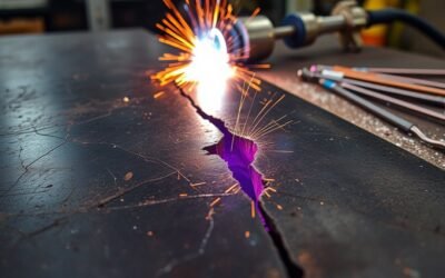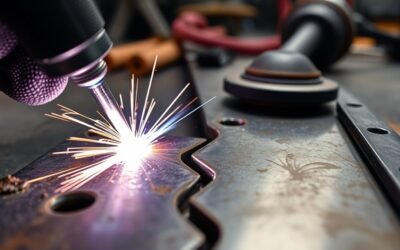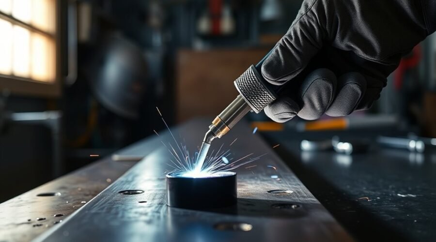
Welding overlap, also called cold lap, happens when weld metal flows beyond the weld toe or root and lies on the base metal without fully fusing to it. It can develop when the weld pool becomes too large or difficult to control, when travel speed is too slow, when the gun or electrode is manipulated incorrectly, or when poor fit-up and surface contamination interfere with fusion. Preventing it requires balanced welding parameters, steady travel, correct joint preparation, and technique that keeps the arc focused where fusion is needed.
Quick Answer
Welding overlap, or cold lap, occurs when weld metal flows past the weld toe or root and rests on the base metal without fusing to it. Common contributors include an oversized weld pool, slow travel, poor gun or electrode manipulation, incorrect settings, poor fit-up, and surface contamination.
Key Takeaways
- Welding overlap is weld metal that extends beyond the intended weld boundary without properly fusing to the parent metal.
- There is no single universal amperage, travel speed, or electrode angle that prevents overlap; settings depend on the process, material, position, joint, filler, and welding procedure.
- Slow travel, an oversized weld pool, poor electrode or gun manipulation, excessive deposition, contamination, and poor fit-up can all contribute.
- Overlap should not be confused with undercut or simple excess reinforcement because the defining problem is unfused metal at the toe or root.
- Repair normally involves removing the defective metal to sound material, inspecting the area, correcting the cause, and rewelding under the applicable procedure.
At a Glance
| Time Required | A small accessible repair may take less than an hour, but inspection, cooling, preparation, and code-required testing can add substantial time. |
| Difficulty | Intermediate to advanced; structural, pressure-containing, or code-controlled repairs should follow an approved repair procedure. |
| Tools Needed | Required PPE, grinder or approved gouging equipment, cleaning tools, welding machine and filler, plus any inspection equipment required by the job or WPS. |
| Cost | Varies widely. A minor shop repair may use only normal consumables, while coded repairs can require qualified labor and nondestructive examination. |
What Is Welding Overlap?
TWI describes overlap as an imperfection at the toe or root of a weld where weld metal flows onto the surface of the parent metal without fusing to it. The visible result is often a rolled or protruding edge that does not blend smoothly into the surrounding base metal.
In practical terms, welding overlap means that deposited metal has reached an area that the arc did not adequately fuse. This is why overlap is more than a cosmetic bead-shape problem. The edge of the deposited metal may conceal an unfused interface underneath it.
The defining feature of overlap is not simply a large bead; it is weld metal extending over parent metal without proper fusion at the interface.
Overlap can occur in both fillet and butt welds and may appear at the weld toe or root. Whether a particular discontinuity is formally rejectable depends on the applicable code, specification, drawing, contract requirements, and welding procedure. In many quality-controlled applications, overlap is not permitted because it represents an unfused condition and an undesirable weld profile.
What Causes Welding Overlap?
Overlap develops when weld metal moves beyond the area where the arc is producing adequate fusion. The exact cause varies by welding process, joint type, position, filler size, material, and operator technique. A large or poorly controlled weld pool is a common contributor, but insufficient fusion at the weld toe can also allow deposited metal to lie on the surface rather than bond to it.
| Factor | Effect | Typical Correction |
|---|---|---|
| Oversized or poorly controlled weld pool | Metal can roll ahead of or beyond the arc | Correct current, voltage, wire feed or deposition rate for the procedure |
| Slow travel speed | Excess metal and heat accumulate in one area | Increase travel speed within the approved range |
| Incorrect gun or electrode angle | Arc force and heat are directed away from the required fusion zone | Correct work and travel angles for the process and joint |
| Poor fit-up | Misalignment or inconsistent gaps make the pool harder to control | Correct joint alignment and preparation before welding |
| Rust, scale, oil, paint, or other contamination | Surface contamination can interfere with fusion and arc stability | Clean the weld zone as required by the procedure |
| Insufficient effective heat at the weld toe | Deposited metal can remain unfused at the edge | Correct arc placement and parameters rather than simply increasing amperage |
The important point is balance. Too little effective fusion at the toe is a problem, but simply increasing current is not always the answer. Excessive current, excessive deposition, or travel that is too slow can enlarge the weld pool enough to make it difficult to control.
Too Much Amperage
Excessive current can contribute to overlap in some welding conditions because it can increase melting and enlarge the weld pool. When the pool becomes too large for the joint, position, or travel speed, molten metal may move beyond the area where the arc is producing sound fusion.
However, amperage should never be diagnosed by itself. In MIG welding, for example, wire feed speed strongly affects welding current and deposition rate. Voltage, stickout, travel speed, material thickness, joint geometry, and welding position also influence bead shape and fusion.
Use the welding procedure specification, filler-metal data, machine chart, or established procedure as the starting point. Then make test welds where permitted and evaluate the bead for proper tie-in, penetration, contour, and arc stability.
Note: Both inadequate fusion and an oversized weld pool can produce poor tie-in. Do not assume that every overlap problem should be corrected by raising or lowering amperage without checking the rest of the welding variables.
Slow Travel Speed Causes Buildup
Reduced travel speed keeps the arc and filler metal in one area longer. If deposition continues faster than the weld can progress along the joint, the bead grows larger and the pool can begin to roll ahead of the arc or spill beyond the intended weld boundary.
Miller’s weld-defect troubleshooting guidance specifically identifies incorrect travel speed as a contributor to cold lap and notes that increasing travel speed can help prevent the weld from overfilling the toes.
The solution is not simply to weld as fast as possible. Travel must remain slow enough for the arc to melt and fuse the joint surfaces properly while being fast enough to prevent excessive buildup.
Travel Speed And Buildup
When travel speed falls below the appropriate range for the process, the weld pool receives more molten filler per unit length. The bead becomes wider or more convex, and excess material may move toward the weld toe before the arc can properly fuse that area.
Increasing travel speed within the approved procedure can reduce this buildup. The correct rate depends on the welding process, current, voltage, filler size, deposition rate, material thickness, joint geometry, and position.
There is no universal travel speed that works for every weld. The correct target is the speed that maintains a stable leading edge on the puddle, adequate sidewall fusion, and the bead dimensions required by the procedure.
Pool Overflow Risk
Slow movement can allow filler metal to accumulate faster than the operator can advance the arc. The enlarged weld pool may then flow onto adjacent base metal without proper fusion, creating overlap.
- Watch the leading edge of the puddle rather than allowing the arc to become buried behind a large pool.
- Keep deposition rate and travel speed balanced.
- Maintain the work and travel angles specified for the process and joint.
- Check the finished weld toe for smooth tie-in instead of a rolled edge.
Overlap can reduce weld quality and may be rejectable under the applicable specification. It should not be described as automatically causing cracking, because the actual consequence depends on the joint, loading, material, defect size, and service conditions.
Faster Passes Prevent Overlap
A moderately faster pass can help when the existing problem is excessive dwell time and filler buildup. Advancing the arc sooner keeps the pool smaller and reduces the amount of molten metal accumulating at the toe.
Excessive speed creates a different set of problems. If the arc moves too quickly, the weld may become narrow and inconsistent, with inadequate penetration or poor tie-in at the toes. The goal is therefore a controlled travel speed, not maximum speed.
Pro Tip: If overlap appears during a practice weld, change one variable at a time. Correcting travel speed first while keeping other approved settings constant makes it easier to see whether excessive dwell time is the main cause.
Wrong Electrode Size or Angle
An oversized electrode or an unnecessarily high deposition rate can make the puddle harder to control in a small joint. The filler size should match the welding process, material thickness, joint preparation, position, and procedure.
Angle also matters, but there is no universal 10°–15° rule for all welding. Welders normally manage two different angles:
- Work angle: the angle of the electrode or gun relative to the pieces forming the joint.
- Travel angle: the amount the electrode or gun is tilted in the direction of or away from travel.
The correct combination changes with process and joint type. For example, a fillet weld on a lap joint uses a different work angle from a butt weld. Follow the WPS or process-specific guidance instead of applying one angle to every weld.
Incorrect manipulation can direct arc energy away from the weld toe while filler metal continues to deposit there. The result can be a rolled edge with incomplete fusion underneath.
Poor Fit-Up and Surface Prep
Poor fit-up can create gaps, misalignment, irregular edges, or inconsistent joint geometry. These conditions change how the arc and weld pool behave and can force the operator to deposit excess metal in one area to compensate.
Surface condition is equally important. Rust, mill scale, oil, paint, moisture, and other contaminants can affect arc stability or prevent reliable fusion. Preparation requirements vary by material and process, but the weld zone should be cleaned to the level required by the welding procedure and filler-metal instructions.
Burrs and uneven edges can also make it harder to maintain consistent arc placement. Before welding, verify alignment, root opening where applicable, edge preparation, cleanliness, and tack-weld condition.
How to Identify Welding Overlap
Overlap is usually first noticed visually as a lip, shelf, or rolled edge of weld metal at the toe. Instead of blending smoothly into the base metal, the bead appears to sit on top of it.
Look for these signs:
- A sharp or rolled transition at the weld toe.
- Weld metal extending beyond the expected bead boundary.
- A visible line or crevice beneath the edge of the deposited metal.
- An excessively large bead combined with poor toe tie-in.
- Localized overlap on the lower side of horizontal or out-of-position welds where gravity has affected the pool.
Visual examination can identify obvious surface overlap, but it cannot prove that all underlying fusion is sound. Critical work may require additional inspection under the applicable code or procedure.
Welding Overlap vs. Similar Weld Defects
| Condition | What It Looks Like | Key Difference |
|---|---|---|
| Overlap | Weld metal rolls onto the base metal at the toe or root | The extended metal is not properly fused to the underlying parent metal |
| Undercut | A groove is melted into the base metal next to the weld toe | Base metal is missing rather than covered by unfused weld metal |
| Excess reinforcement | The weld face is higher or more convex than required | A high bead does not automatically mean the toe is unfused |
| Lack of fusion | Weld metal fails to fuse to a joint face or previous bead | It can occur internally; overlap is a specific surface shape associated with unfused metal at a toe or root |
How to Prevent Welding Overlap
Preventing overlap begins with controlling heat, deposition, puddle size, and arc placement. The correct settings are process-specific, so start with the approved WPS or established procedure rather than a universal amperage or travel-speed number.
- Prepare the joint correctly. Remove contaminants as required and correct major gaps, misalignment, burrs, and edge problems before welding.
- Use the correct filler or electrode size. Avoid a deposition rate that overwhelms a small joint or difficult welding position.
- Set the machine for the procedure. Match current, voltage, wire feed speed, polarity, gas, stickout, and other variables to the process and material.
- Maintain the correct work and travel angles. Keep the arc directed into the area that must fuse rather than allowing filler metal to roll ahead of it.
- Control travel speed. Avoid lingering long enough for the puddle to become excessively large, but do not travel so fast that sidewall fusion is lost.
- Watch the puddle edges. The weld should tie smoothly into the parent metal instead of creating a lip or shelf at the toe.
- Use test welds when permitted. Verify bead shape and fusion before committing to production work.
A sound weld toe should transition smoothly into the base metal without a rolled edge of unfused weld metal.
How to Fix Welding Overlap
Correcting welding overlap normally requires removal of the defective metal, verification that the affected area has been fully removed, correction of the original welding problem, and rewelding under the applicable procedure.
Warning: Structural, pressure-containing, load-critical, or code-controlled welds should be repaired only under the applicable approved procedure. Grinding or gouging too deeply can reduce base-metal or weld thickness. Wear suitable eye, face, hand, hearing, and body protection, control sparks, and use appropriate welding-fume ventilation.
TWI’s repair guidance for fusion defects describes localized grinding or gouging followed by rewelding as a normal remedial approach.
- Stop and identify the cause. Check travel speed, arc placement, amperage or wire feed, voltage, filler size, joint fit-up, surface condition, and welding position.
- Remove the overlap. Grind or gouge the affected area to sound metal using the method permitted by the repair procedure. Do not merely smooth the visible lip while leaving an unfused interface underneath.
- Blend the repair area. Remove sharp transitions and prepare the groove or surface so it can be rewelded without trapping slag or leaving inaccessible edges.
- Clean and inspect. Remove grinding debris, scale, oil, and other contamination. Inspect the prepared area and use any required NDT before rewelding.
- Correct the welding variables. Adjust the actual cause rather than automatically changing one setting. A slow-travel problem may require faster movement, while poor toe fusion may require different arc placement or procedure settings.
- Reweld under the applicable procedure. Maintain the required electrode or gun angles, travel speed, interpass controls, filler, and machine settings.
- Inspect the completed repair. Confirm smooth toe transition, correct weld size and profile, and any code-required acceptance criteria or NDT.
Do not continue repeatedly grinding and rewelding a critical joint without identifying why the defect keeps returning. Persistent overlap can indicate a welding-procedure, access, fit-up, equipment, or technique problem that needs correction before further repair.
Inspection and Acceptance of Welding Overlap
Visible overlap can often be found during visual inspection because of its rolled-edge profile. More demanding work may require penetrant testing, magnetic particle testing, ultrasonic testing, radiography, or another examination method depending on the material, joint, suspected discontinuity, and governing specification.
There is no single acceptance limit that applies to every welded product. The allowable condition must be determined from the drawing, welding code, project specification, contract, or other governing document. TWI notes that standards rarely permit overlap except in limited circumstances.
For production or code work, the safest approach is to treat suspected overlap as a condition requiring evaluation rather than assuming that a visually small defect is automatically acceptable.
Safety During Welding and Repair
Grinding and rewelding introduce hazards beyond the defect itself. Grinding produces sparks and flying particles, while welding exposes workers to intense radiation, hot metal, fumes, gases, and electrical hazards.
OSHA’s welding ventilation requirements call for appropriate ventilation where required to keep fumes and smoke within safe limits. CCOHS welding-fume guidance recommends controlling fumes at the source with local exhaust ventilation and using respiratory protection when required by the workplace respiratory-protection program.
Use appropriate welding helmet shade, safety glasses under the helmet where required, gloves, protective clothing, hearing protection for grinding, and suitable ventilation. Never rely on food or beverages as protection against welding fumes.
Frequently Asked Questions
Why Do Welders Drink Milk After Welding?
Some welders have traditionally drunk milk after welding because of a belief that it helps with fume exposure. Milk can provide normal nutrition and hydration, but it is not a control measure for welding fumes and should not be treated as an antidote. Fume exposure should be controlled with ventilation, source capture, safe work practices, and respiratory protection when required. Anyone who develops concerning symptoms after welding-fume exposure should follow workplace medical procedures or seek appropriate medical evaluation.
What Causes Overlap?
Overlap is commonly associated with a weld pool that is too large or difficult to control, slow travel, excessive deposition, poor gun or electrode manipulation, incorrect arc placement, poor fit-up, and contaminated surfaces. The exact cause is process-specific, so the complete welding setup should be checked rather than changing only amperage.
What Is the Definition of Overlap in Welding?
Overlap is a weld imperfection in which weld metal extends beyond the weld toe or root and lies on the parent metal without properly fusing to it. It is also commonly called cold lap.
When Two Members Overlap, the Best Weld Joint to Use Is?
When two workpieces overlap, the joint configuration is called a lap joint. Lap joints are commonly welded with fillet welds. The required weld size, length, number of welded sides, and joint dimensions depend on the design and applicable specification. Miller’s weld-joint guide identifies lap joints as overlapping members that are commonly fillet welded.
Is Welding Overlap the Same as Lack of Fusion?
Overlap includes an unfused interface where weld metal has flowed onto the parent metal, so lack of fusion is part of the problem. However, lack of fusion is a broader category that can also occur internally between weld passes or along joint sidewalls without creating visible overlap.
Can Welding Overlap Just Be Ground Smooth?
Not necessarily. Grinding only the visible lip can leave the unfused interface underneath. A proper repair removes the defective area to sound metal, inspects the prepared surface, corrects the original cause, and rewelds when required by the governing procedure.
Conclusion
Welding overlap is a recognizable defect in which deposited weld metal extends beyond the weld toe or root without properly fusing to the underlying parent metal. Slow travel, an oversized puddle, incorrect deposition rate, poor gun or electrode manipulation, contamination, and poor fit-up can all contribute.
Preventing overlap depends on balanced procedure settings, correct arc placement, controlled travel speed, suitable filler size, clean joint preparation, and close attention to toe fusion. Avoid universal settings such as one travel speed or one electrode angle because the correct values change with process, joint, material, position, and procedure.
When overlap occurs, repair should remove the entire unfused area rather than only smoothing its visible edge. Inspect the prepared area, correct the cause, reweld under the applicable procedure, and verify the finished repair before returning a critical joint to service.
Sources
- TWI — A General Review of Geometric Shape Imperfections — definition, causes, avoidance, and acceptance considerations for overlap.
- TWI — Lack of Sidewall and Inter-Run Fusion — welding parameters, cleaning, technique, inspection, and repair guidance.
- Miller — Troubleshooting Common MIG Weld Defects — travel-speed and cold-lap troubleshooting guidance.
- Miller — Guide to the Five Basic Weld Joints — lap-joint and fillet-weld terminology.
- OSHA — Ventilation and Protection in Welding, Cutting, and Heating — workplace ventilation and welding-protection requirements.
- CCOHS — Welding Fumes and Gases — fume-control, ventilation, and respiratory-protection guidance.